Page 188 of 457

Recommended brake fluid
DOT 4
�Use only the designated brak")
4-41
FRONT AND REAR BRAKESCHAS
WARNING
CAUTION:
3. Fill:
�brake fluid reservoir
(with the specified amount of the recom-
mended brake fluid)
Recommended brake fluid
DOT 4
�Use only the designated brake fluid. Other
brake fluids may cause the rubber seals to
deteriorate, causing leakage and poor
brake performance.
�Refill with the same type of brake fluid that
is already in the system. Mixing brake
fluids may result in a harmful chemical
reaction, leading to poor brake perfor-
mance.
�When refilling, be careful that water does
not enter the brake fluid reservoir. Water
will significantly lower the boiling point of
the brake fluid and could cause vapor lock.
Brake fluid may damage painted surfaces
and plastic parts. Therefore, always clean
up any spilt brake fluid immediately.
4. Bleed:
�brake system
Refer to “BLEEDING THE HYDRAULIC
BRAKE SYSTEM“ in chapter 3.
5. Check:
�brake fluid level
Below the minimum level mark
a � Add the
recommended brake fluid to the proper level.
Refer to ”CHECKING THE BRAKE FLUID
LEVEL“ in chapter 3.
6. Check:
�brake lever operation
Soft or spongy feeling � Bleed the brake
system.
Refer to ”BLEEDING THE HYDRAULIC
BRAKE SYSTEM“ in chapter 3.
ProCarManuals.com
Page 190 of 457

Recommended brake fluid
DOT 4
�Use only the designated brak")
4-43
FRONT AND REAR BRAKESCHAS
WARNING
CAUTION:
2. Fill:
�brake fluid reservoir
(with the specified amount of the recom-
mended brake fluid)
Recommended brake fluid
DOT 4
�Use only the designated brake fluid. Other
brake fluids may cause the rubber seals to
deteriorate, causing leakage and poor
brake performance.
�Refill with the same type of brake fluid that
is already in the system. Mixing brake
fluids may result in a harmful chemical
reaction, leading to poor brake perfor-
mance.
�When refilling, be careful that water does
not enter the brake fluid reservoir. Water
will significantly lower the boiling point of
the brake fluid and could cause vapor lock.
Brake fluid may damage painted surfaces
and plastic parts. Therefore, always clean
up any spilt brake fluid immediately.
3. Bleed:
�brake system
Refer to “BLEEDING THE HYDRAULIC
BRAKE SYSTEM” in chapter 3.
4. Check:
�brake fluid level
Below the minimum level mark
a � Add the
recommended brake fluid to the proper level.
Refer to “CHECKING THE BRAKE FLUID
LEVEL” in chapter 3.
5. Check:
�brake pedal operation
Soft or spongy feeling � Bleed the brake
system.
Refer to “BLEEDING THE HYDRAULIC
BRAKE SYSTEM” in chapter 3.
ProCarManuals.com
Page 192 of 457
4-45
FRONT FORKCHAS
Order Job / Part Q’ty Remarks
Disassembling the front fork legs
Cap bolt
O-ring
Damper adjusting rod
Nut
Washer
Spacer
Fork spring
Dust seal
Oil seal clip
Oil seal1
1
1
1
1
1
1
1
1
1Disassemble the parts in the order listed.
The following the procedure applies to
both of the front fork legs.
NOTE:
1
2
3
4
5
6
7
8
9
10
23 Nm (2.3 m�kg, 17 ft�lb)
15 Nm (1.5 m�kg, 11 ft�lb)
23 Nm (2.3 m�kg, 17 ft�lb)
EAS00648
ProCarManuals.com
Page 195 of 457
4-48
FRONT FORKCHAS
NOTE:
WARNING
NOTE:
CAUTION:
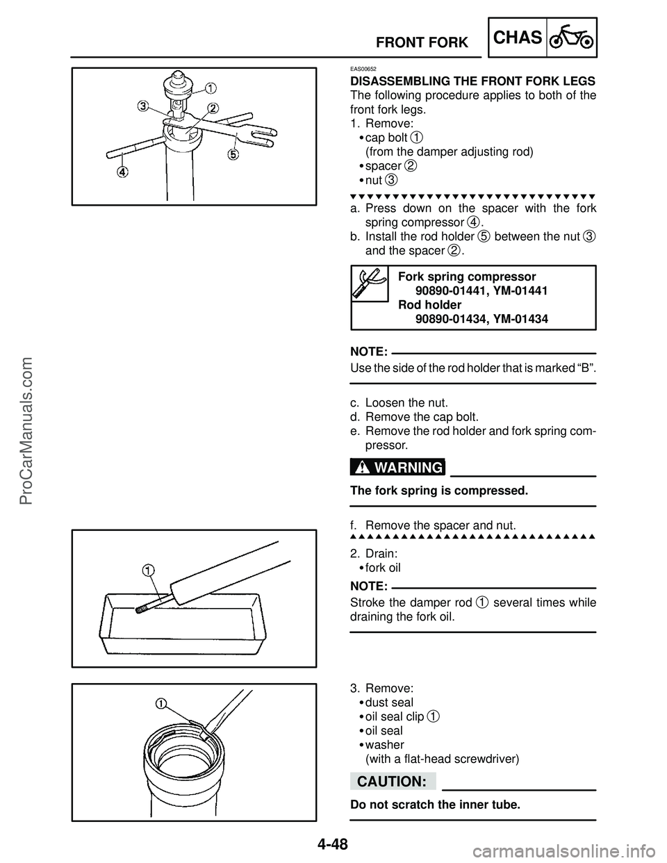
EAS00652
DISASSEMBLING THE FRONT FORK LEGS
The following procedure applies to both of the
front fork legs.
1. Remove:
�cap bolt
1
(from the damper adjusting rod)
�spacer
2
�nut 3
a. Press down on the spacer with the fork
spring compressor
4.
b. Install the rod holder
5 between the nut 3
and the spacer 2.
Fork spring compressor
90890-01441, YM-01441
Rod holder
90890-01434, YM-01434
Use the side of the rod holder that is marked “B”.
c. Loosen the nut.
d. Remove the cap bolt.
e. Remove the rod holder and fork spring com-
pressor.
The fork spring is compressed.
f. Remove the spacer and nut.
2. Drain:
�fork oil
Stroke the damper rod
1 several times while
draining the fork oil.
3. Remove:
�dust seal
�oil seal clip
1
�oil seal
�washer
(with a flat-head screwdriver)
Do not scratch the inner tube.
ProCarManuals.com
Page 196 of 457
4-49
FRONT FORKCHAS
NOTE:
WARNING
4. Remove:
�damper rod assembly bolt
�damper rod assembly
While holding the damper rod assembly with the
damper rod holder
1, loosen the damper rod
assembly bolt.
Damper rod holder
90890-01423, YM-01423
EAS00656
CHECKING THE FRONT FORK LEGS
The following procedure applies to both of the
front fork legs.
1. Check:
�inner tube
1
�outer tube 2
Bends / damage / scratches � Replace.
Do not attempt to straighten a bent inner
tube as this may dangerously weaken it.
2. Measure:
�spring free length
a
Out of specification � Replace.
Spring free length
236.5 mm (9.31 in)
: 231.8 mm (9.13 in)
3. Check:
�damper rod
1
Damage / wear � Replace.
Obstruction � Blow out all of the oil pas-
sages with compressed air.
�damper rod adjusting rod
Bends / damage � Replace.
ProCarManuals.com
Page 197 of 457
4-50
FRONT FORKCHAS
CAUTION:
WARNING
NOTE: �The front fork leg has a built-in damper ad-
justing rod and a very sophisticated inter-
nal construction, which are particularly
sensitive to foreign material.
�When disassembling and assembling the
front fork leg, do not allow any foreign ma-
terial to enter the front fork.
4. Check:
�cap bolt O-ring
1
Damage / wear � Replace.
EAS00659
ASSEMBLING THE FRONT FORK LEGS
The following procedure applies to both of the
front fork legs.
�Make sure the oil levels in both front fork
legs are equal.
�Uneven oil levels can result in poor han-
dling and a loss of stability.
�When assembling the front fork leg, be sure to
replace the following parts:
– outer tube bushing
– oil seal
– dust seal
– Before assembling the front fork leg, make
sure all of the components are clean.
1. Install:
�inner tube
1
�damper rod assembly 2
�damper rod assembly bolt
�copper washer
New
ProCarManuals.com
Page 198 of 457
4-51
FRONT FORKCHAS
WARNING
CAUTION:
23 Nm (2.3 m�kg, 17 ft�lb)
NOTE:
Always use new copper washer.
Allow the damper rod assembly to slide
slowly down the inner tube
1 until it pro-
trudes from the bottom of the inner tube. Be
careful not to damage the inner tube.
2. Lubricate:
�inner tube’s outer surface
Recommended lubricant
Suspension oil “01” or
equivalent
3. Tighten:
�damper rod assembly bolt
1
LOCTITE
While holding the damper rod assembly with the
damper rod holder
2, tighten the damper rod
assembly bolt.
Damper rod holder
90890-01423, YM-01423
4. Install:
�dust seal
1
�oil seal clip 2
�oil seal 3
�washer 4
ProCarManuals.com
Page 199 of 457
4-52
FRONT FORKCHAS
CAUTION:
NOTE:
NOTE:
Make sure the numbered side of the oil seal
faces up.
�Before installing the oil seal, lubricate its lips
with lithium-soap-based grease.
�Lubricate the outer surface of the inner tube
with fork oil.
�Before installing the oil seal, cover the top of
the front fork leg with a plastic bag to protect
the oil seal during installation.
5. Install :
�Oil seal
1
(with the fork seal driver 2)
Fork seal driver
90890-01442, YM-01442
6. Install:
�oil seal clip
1
Adjust the oil seal clip so that it fits into the outer
tube’s groove.
7. Install:
�dust seal
1
(with the fork seal driver weight 2)
Fork seal driver
90890-01442m YM-01442
ProCarManuals.com