Page 122 of 457
3-45
ADJUSTING THE REAR BRAKE LIGHT SWITCH /
CHECKING THE FRONT AND REAR BRAKE PADSCHK
ADJ
NOTE:
a
b
EAS00128
ADJUSTING THE REAR BRAKE LIGHT
SWITCH
The rear brake light switch is operated by move-
ment of the brake pedal.
The rear brake light switch is properly adjusted
when the brake light comes on just before the
braking effect starts.
1. Check:
�rear brake light operation timing
Incorrect � Adjust.
2. Adjust:
�rear brake light operation timing
a. Hold the main body
1 of the rear brake light
switch so that it does not rotate and turn the
adjusting nut
2 in direction a or b until the
rear brake light comes on at the proper time.
Direction
Brake light comes on
sooner.
DirectionBrake light comes on
later.
EAS00122
CHECKING THE FRONT AND REAR BRAKE
PADS
The following procedure applies to all of the
brake pads.
1. Operate the brake.
ProCarManuals.com
Page 137 of 457
3-60
CHECKING THE TIRES / CHECKING THE WHEELS
CHK
ADJ
WARNING
NOTE:
WARNING
NOTE: Front tire
Manufacturer
SizeModel
DUNLOP120 / 70ZR 17
M / C (58W)D218FL
MICHELIN120 / 70ZR 17
M / C (58W)Pilot
POWER C
Rear tire
Manufacturer
SizeModel
DUNLOP190 / 50ZR 17
M / C (73W)D218L
MICHELIN190 / 50ZR 17
M / C (73W)Pilot
POWER G
New tires have a relatively low grip on the
road surface until they have been slightly
worn. Therefore, approximately 100 km
should be traveled at normal speed before
any high-speed riding is done.
For tires with a direction of rotation mark
1:
�Install the tire with the mark pointing in the
direction of wheel rotation.
�Align the mark
2 with the valve installation
point.
EAS00168
CHECKING THE WHEELS
The following procedure applies to both of the
wheels.
1. Check:
�wheel
Damage / out-of-round � Replace.
Never attempt to make any repairs to the
wheel.
After a tire or wheel has been changed or re-
placed, always balance the wheel.
ProCarManuals.com
Page 139 of 457

3-62
CHECKING AND CHARGING THE BATTERY
CHK
ADJ
WARNING
CAUTION:
EAS00178
ELECTRICAL SYSTEM
CHECKING AND CHARGING THE BATTERY
Batteries generate explosive hydrogen gas
and contain electrolyte which is made of poi-
sonous and highly caustic sulfuric acid.
Therefore, always follow these preventive
measures:
�Wear protective eye gear when handling or
working near batteries.
�Charge batteries in a well-ventilated area.
�Keep batteries away from fire, sparks or
open flames (e.g., welding equipment,
lighted cigarettes).
�DO NOT SMOKE when charging or han-
dling batteries.
�KEEP BATTERIES AND ELECTROLYTE
OUT OF REACH OF CHILDREN.
�Avoid bodily contact with electrolyte as it
can cause severe burns or permanent eye
injury.
FIRST AID IN CASE OF BODILY CONTACT:
EXTERNAL
�Skin – Wash with water.
�Eyes – Flush with water for 15 minutes and
get immediate medical attention.
INTERNAL
�Drink large quantities of water or milk fol-
lowed with milk of magnesia, beaten egg or
vegetable oil. Get immediate medical atten-
tion.
�This is a sealed battery. Never remove the
sealing caps because the balance between
cells will not be maintained and battery per-
formance will deteriorate.
�Charging time, charging amperage and
charging voltage for an MF battery are dif-
ferent from those of conventional batter-
ies. The MF battery should be charged as
explained in the charging method illustra-
tions. If the battery is overcharged, the
electrolyte level will drop considerably.
Therefore, take special care when charging
the battery.
ProCarManuals.com
Page 145 of 457
3-68
CHECKING THE FUSES
CHK
ADJ
WARNING
Pocket tester
90890-03112, YU-3112
b. If the pocket tester indicates “∞”, replace the
fuse.
3. Replace:
�blown fuse
a. Set the main switch to “OFF”.
b. Install a new fuse of the correct amperage
rating.
c. Set on the switches to verify if the electrical
circuit is operational.
d. If the fuse immediately blows again, check
the electrical circuit.
Fuses
Amperage
ratingQ’ty
Main50 A1
Fuel injection
system15 A1
Headlight25 A1
Signaling
system10 A1
Ignition15 A1
Backup fuse
(odometer
and clock)
10 A1
Radiator
fan motor15 A2
Reserve25 A, 15 A,
10 A1
Never use a fuse with an amperage rating
other than that specified. Improvising or us-
ing a fuse with the wrong amperage rating
may cause extensive damage to the electri-
cal system, cause the lighting and ignition
systems to malfunction and could possibly
cause a fire.
4. Install:
�front cowling inner panel (left)
Refer to “COWLINGS”.
�rider seat
Refer to “SEATS”.
ProCarManuals.com
Page 146 of 457
3-69
A
A
B
B
B
REPLACING THE HEADLIGHT BULBS
CHK
ADJ
WARNING
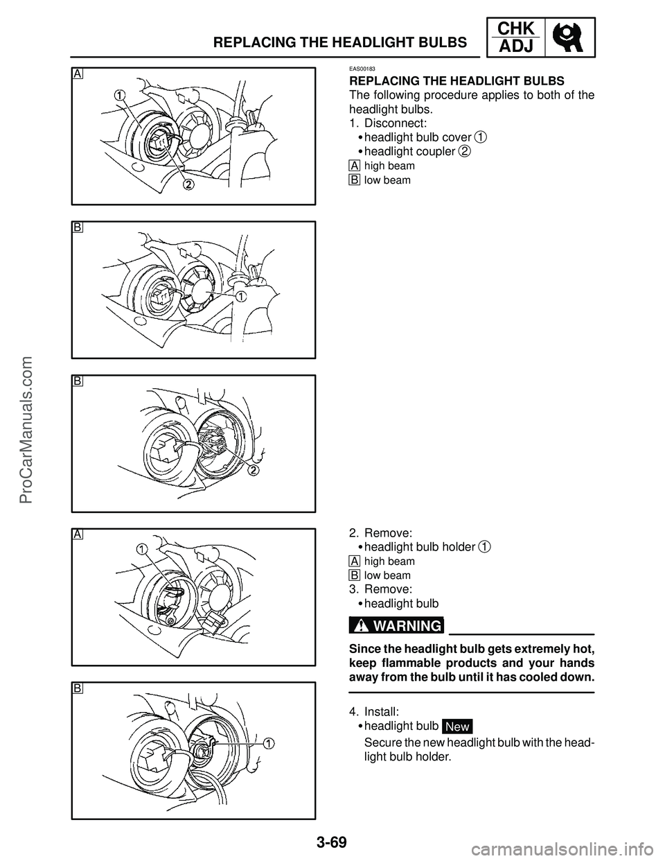
EAS00183
REPLACING THE HEADLIGHT BULBS
The following procedure applies to both of the
headlight bulbs.
1. Disconnect:
�headlight bulb cover
1
�headlight coupler 2
Ahigh beam
Blow beam
2. Remove:
�headlight bulb holder
1
Ahigh beam
Blow beam
3. Remove:
�headlight bulb
Since the headlight bulb gets extremely hot,
keep flammable products and your hands
away from the bulb until it has cooled down.
4. Install:
�headlight bulb
New
Secure the new headlight bulb with the head-
light bulb holder.
ProCarManuals.com
Page 147 of 457

3-70
REPLACING THE HEADLIGHT BULBS /
ADJUSTING THE HEADLIGHT BEAMSCHK
ADJ
CAUTION:
a
b
a
b
Avoid touching the glass part of the head-
light bulb to keep it free from oil, otherwise
the transparency of the glass, the life of the
bulb and the luminous flux will be adversely
affected. If the headlight bulb gets soiled,
thoroughly clean it with a cloth moistened
with alcohol or lacquer thinner.
5. Install:
�headlight bulb holder
6. Install:
�headlight bulb cover (high beam)
�headlight bulb coupler (low beam)
7. Connect:
�headlight coupler (high beam)
�headlight cover (low beam)
EAS00185
ADJUSTING THE HEADLIGHT BEAMS
The following procedure applies to both of the
headlights.
1. Remove:
�front cowling inner panels
Refer to “COWLINGS”.
2. Adjust:
�headlight beam (vertically)
a. Turn the adjusting screw
1 in direction a or
b.
Direction
Headlight beam is raised.
DirectionHeadlight beam is
lowered.
3. Adjust:
�headlight beam (horizontally)
a. Turn the adjusting screw
2 in direction a or
b.
Direction
Headlight beam moves to
the left.
DirectionHeadlight beam moves to
the right.
4. Install:
�front cowling inner panels
Refer to “COWLINGS”.
ProCarManuals.com
Page 155 of 457
4-8
FRONT WHEEL AND BRAKE DISCSCHAS
NOTE:
3. Adjust:
�front wheel static balance
a. Install a balancing weight
1 onto the rim ex-
actly opposite the heavy spot “X”.
Start with the lightest weight.
b. Turn the front wheel 90� so that the heavy
spot is positioned as shown.
c. If the heavy spot does not stay in that posi-
tion, install a heavier weight.
d. Repeat steps (b) and (c) until the front wheel
is balanced.
4. Check:
�front wheel static balance
a. Turn the front wheel and make sure it stays at
each position shown.
b. If the front wheel does not remain stationary
at all of the positions, rebalance it.
ProCarManuals.com
Page 170 of 457
4-23
FRONT AND REAR BRAKESCHAS
Order Job / Part Q’ty Remarks
10
11
12
13
14Copper washer
Brake hose
Brake master cylinder bracket
Brake master cylinder
Front brake light switch2
1
1
1
1
For installation, reverse the removal
procedure.
3.8 Nm (0.38 m�kg, 2.7 ft�lb)
1.2 Nm (0.12 m�kg, 0.9 ft�lb)
13 Nm (1.3 m�kg, 9.4 ft�lb)
30 Nm (3.0 m�kg, 22 ft�lb)
ProCarManuals.com

D218FL
MICHELIN120 / 70ZR 17
M / C (58W)Pilot
POWER C")