Page 394 of 506

5 - 35
CHAS
13. Check:
�Inner tube smooth movement
Tightness/binding/rough spots → Repeat
the steps 2 to 12.
5PA51080
14. Compress the front fork fully.
15. Fill:
�Front fork oil
Until outer tube top surface with recom-
mended fork oil 1.
CAUTION:
�Be sure to use recommended fork oil. If
other oils are used, they may have an
excessively adverse effect on the front
fork performance.
�Never allow foreign materials to enter the
front fork.
Recommended oil:
Suspension oil “01”
5PA51090
16. After filling, pump the damper rod 1 slowly
up and down more than 10 times to distrib-
ute the fork oil.
17. Fill:
�Front fork oil
Until outer tube top surface with recom-
mended fork oil once more.
5PA51100
18. After filling, pump the outer tube 1 slowly
up and down (about 150 mm (5.9 in)
stroke) to distribute the fork oil once more.
NOTE:
Be careful not to excessive full stroke. A stroke
of 150 mm (5.9 in) or more will cause air to
enter. In this case, repeat the steps 15 to 18.
5PA51110
FRONT FORK
Page 396 of 506

5 - 36
CHAS
19. Wait ten minutes until the air bubbles have
been removed from the front fork, and the
oil has dispense evenly in system before
setting recommended oil level.
NOTE:
Fill with the fork oil up to the top end of the
outer tube, or the fork oil will not spread over to
every part of the front forks, thus making it
impossible to obtain the correct level.
Be sure to fill with the fork oil up to the top of
the outer tube and bleed the front forks.
20. Measure:
�Oil level (left and right) a
Out of specification → Adjust.
NOTE:
Be sure to install the spring guide 2 when
checking the oil level.
WARNING
Never fail to make the oil level adjustment
between the maximum and minimum level
and always adjust each front fork to the
same setting. Uneven adjustment can
cause poor handling and loss of stability.
Standard oil level:
90 mm (3.54 in)
Extent of adjustment:
80 ~ 120 mm (3.15 ~ 4.72 in)
From top of outer tube with
inner tube and damper rod 1
fully compressed without
spring.
5PA51120
FRONT FORK
Page 410 of 506
5 - 43
CHAS
EC5B5000
ASSEMBLY AND INSTALLATION
Handlebar
1. Install:
�Handlebar 1
�Handlebar upper holder 2
�Bolt (handlebar upper holder) 3
NOTE:
�The handlebar upper holder should be
installed with the punched mark a forward.
�First tighten the bolts on the front side of the
handlebar upper holder, and then tighten the
bolts on the rear side.
5PA51330
T R..27 Nm (2.7 m · kg, 19 ft · lb)
5PA51340
2. Install:
�Left grip 1
Apply the adhesive to the handlebar 2.
NOTE:
�Before applying the adhesive, wipe off
grease or oil on the handlebar surface a
with a lacquer thinner.
�Install the left grip to the handlebar so that
the arrow mark (L) faces straight upward.5PA51350
3. Install:
�Right grip 1
Apply the adhesive on the tube guide 2.
NOTE:
�Before applying the adhesive, wipe off
grease or oil on the tube guide surface a
with a lacquer thinner.
�Locate the mating mark b on the grip as
shown.5PA51360
5PA51370
HANDLEBAR
Page 428 of 506
5 - 52
CHAS
EC578000
SWINGARM DISASSEMBLY
5PAR0020
Extent of removal:
1 Swingarm disassembly
2 Connecting rod removal and disassembly
3 Relay arm removal and disassembly
Extent of removal Order Part name Q’ty Remarks
SWINGARM DISASSEMBLY
1 Relay arm 1
2 Connecting rod 1
3 Cover 2
4 Dust seal 2
5 Collar 5
6 Bushing 4
7 Oil seal 8
8 Bearing 9
Refer to “REMOVAL POINTS”.
9 Bushing (swingarm)
2
1
2
2
3
3
SWINGARM
Page 430 of 506
5 - 53
CHAS
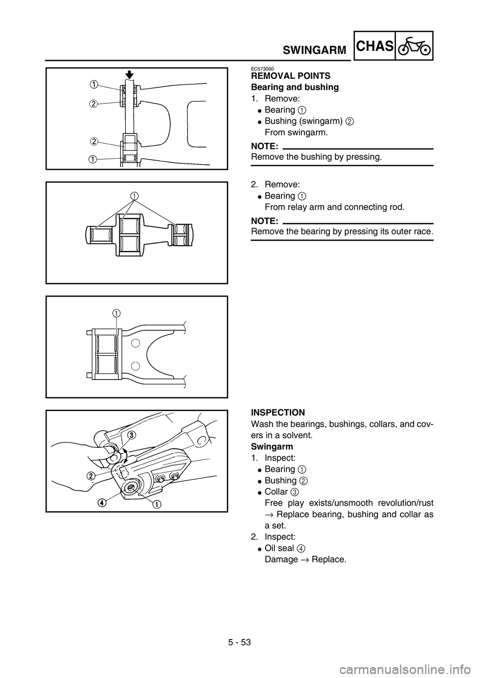
EC573000
REMOVAL POINTS
Bearing and bushing
1. Remove:
�Bearing 1
�Bushing (swingarm) 2
From swingarm.
NOTE:
Remove the bushing by pressing.5PA51640
2. Remove:
�Bearing 1
From relay arm and connecting rod.
NOTE:
Remove the bearing by pressing its outer race.
5PAR0021
1
5PAR0022
INSPECTION
Wash the bearings, bushings, collars, and cov-
ers in a solvent.
Swingarm
1. Inspect:
�Bearing 1
�Bushing 2
�Collar 3
Free play exists/unsmooth revolution/rust
→ Replace bearing, bushing and collar as
a set.
2. Inspect:
�Oil seal 4
Damage → Replace.
5PA51680
SWINGARM
Page 432 of 506
 2
�Bushing 3
Free play exists/unsmooth revolution/rust
→ Replace bearing and bushing as a set.
2. Inspect:
�Bearing (polylu")
5 - 54
CHAS
Relay arm
1. Inspect:
�Bearing 1
�Bearing (polylube bearing) 2
�Bushing 3
Free play exists/unsmooth revolution/rust
→ Replace bearing and bushing as a set.
2. Inspect:
�Bearing (polylube bearing) 2
Loss of solid lubrication → Replace.
�Oil seal 4
Damage → Replace.
NOTE:
Polylube bearings, with solid lubrication, have
been adopted with the intent to make the nee-
dle bearings, used in this model, maintenance
free. With polylube bearings, no grease nipple
and regular lubrication is necessary. However,
grease should be applied to all oil seals and
collars when removed or installed.
Connecting rod
1. Inspect:
�Bearing 1
�Bushing 2
Free play exists/unsmooth revolution/rust
→ Replace bearing and bushing as a set.
2. Inspect:
�Oil seal 3
Damage → Replace.
5PAR0023
5PA51700
EC575000
ASSEMBLY AND INSTALLATION
Bearing, bushing and oil seal
1. Install:
�Bearing 1
�Bushing (swingarm) 2
�Oil seal 3
To swingarm.
NOTE:
�Apply the molybdenum disulfide grease on
the bearing and bushing when installing.
�Install the bearing by pressing it on the side
having the manufacture’s marks or numbers.
�First install the bushing and then the bearing
to a specified depth from inside.
Installed depth of bearings and
bushings:
Bearing a: 4.5 mm (0.18 in)
Bushing b: 4.5 mm (0.18 in)
5PA51730
5PA51740
SWINGARM
Page 434 of 506
5 - 55
CHAS
2. Install:
�Bearing 1
�Oil seal 2
To relay arm.
NOTE:
�Apply the molybdenum disulfide grease on
the bearing when installing.
�Install the bearing by pressing it on the side
having the manufacture’s marks or numbers.
Installed depth of bearings:
Depth a: 4.5 mm (0.18 in)
Depth b: 0.5 mm (0.02 in)
Depth c: 4.0 mm (0.16 in)
5PA51750
5PA51760
c1
3. Install:
�Bearing 1
�Oil seal 2
To connecting rod.
NOTE:
�Apply the molybdenum disulfide grease on
the bearing when installing.
�Install the bearing by pressing it on the side
having the manufacture’s marks or numbers.
Installed depth of bearings a:
6.5 mm (0.26 in)
5PA51760
Swingarm
1. Install:
�Collar 1
To swingarm 2.
NOTE:
Apply the molybdenum disulfide grease on the
collars, bearings, bushings and oil seal lips.
5PA51770
SWINGARM
Page 436 of 506
5 - 56
CHAS
2. Install:
�Bushing 1
�Collar 2
�Dust seal 3
�Cover 4
To relay arm 5.
NOTE:
Apply the molybdenum disulfide grease on the
bushings, dust seals, collars, cover lips, bear-
ings and oil seal lips.
3. Install:
�Bushing 1
To connecting rod 2.
NOTE:
Apply the molybdenum disulfide grease on the
bushings, bearings and oil seal lips.
5PAR0025
5PA51790
4. Install:
�Connecting rod 1
�Washer 2
�Bolt (connecting rod) 3
�Nut (connecting rod) 4
To swingarm 5.
NOTE:
Apply the molybdenum disulfide grease on the
bolt.
5PA51800
T R..53 Nm (5.3 m · kg, 38 ft · lb)
5. Install:
�Relay arm 1
�Bolt (relay arm) 2
�Nut (relay arm) 3
NOTE:
Apply the molybdenum disulfide grease on the
bolt.
5PA51810
T R..54 Nm (5.4 m · kg, 39 ft · lb)
SWINGARM