Page 41 of 82

PERIODIC MAINTENANCE AND MINOR REPAIR
6-8
6
EAU19751
Engine oil and oil filter
element The engine oil level should be checked
before each ride. In addition, the oil
must be changed and the oil filter ele-
ment replaced at the intervals specified
in the periodic maintenance and lubri-
cation chart.
To check the engine oil level
1. Place the vehicle on a level sur-
face and hold it in an upright posi-
tion.NOTE:
Make sure that the vehicle is positioned
straight up when checking the oil level.
A slight tilt to the side can result in afalse reading.
2. Start the engine, warm it up for
several minutes, and then turn it
off.
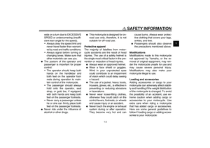
3. Wait a few minutes until the oil set-
tles, and then check the oil level
through the check window located
at the bottom-right side of the
crankcase.
NOTE:The engine oil should be between theminimum and maximum level marks.
4. If the engine oil is below the mini-
mum level mark, add sufficient oil
of the recommended type to raise
it to the correct level.
To change the engine oil (with or
without oil filter element replace-
ment)
1. Start the engine, warm it up for
several minutes, and then turn it
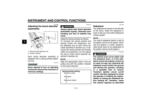
off.2. Place an oil pan under the engine
to collect the used oil.
3. Remove the engine oil filler cap
and drain bolt to drain the oil from
the crankcase.
NOTE:Skip steps 4–6 if the oil filter element isnot being replaced.
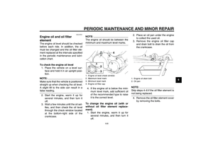
4. Remove the oil filter element cover
by removing the bolts.
1. Engine oil level check window
2. Maximum level mark
3. Minimum level mark
4. Engine oil filler cap
1. Engine oil drain bolt
2. Oil pan
5KRE2.book Page 8 Monday, June 23, 2003 3:32 PM
Page 42 of 82

PERIODIC MAINTENANCE AND MINOR REPAIR
6-9
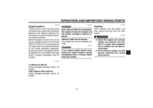
65. Remove and replace the oil filter
element and O-ring.
6. Install the oil filter element cover by
installing the bolts, then tightening
them to the specified torque.
NOTE:
Make sure that the O-ring is properlyseated.
7. Install the engine oil drain bolt, and
then tighten it to the specified
torque.
8. Add the specified amount of the
recommended engine oil, and then
install and tighten the oil filler cap.
CAUTION:
ECA11620
�
In order to prevent clutch slip-
page (since the engine oil also
lubricates the clutch), do not
mix any chemical additives. Do
not use oils with a diesel speci-
fication of “CD” or oils of a high-
er quality than specified. In
addition, do not use oils labeled
“ENERGY CONSERVING II” or
higher.
�
Make sure that no foreign mate-rial enters the crankcase.
9. Start the engine, and then let it idle
for several minutes while checking
it for oil leakage. If oil is leaking, im-
mediately turn the engine off and
check for the cause.
10. Turn the engine off, and then
check the oil level and correct it if
necessary.
1. Bolt
1. Oil filter element
2. O-ring
Tightening torque:
Oil filter element cover bolt:
10 Nm (1.0 m·kgf, 7.2 ft·lbf)
Tightening torque:
Engine oil drain bolt:
34 Nm (3.4 m·kgf, 25 ft·lbf)
Recommended engine oil:
See page 8-1.
Oil quantity:
With oil filter element replacement:
1.60 L (1.69 US qt) (1.41 Imp.qt)
Without oil filter element replace-
ment:
1.40 L (1.48 US qt) (1.23 Imp.qt)
5KRE2.book Page 9 Monday, June 23, 2003 3:32 PM
Page 43 of 82

PERIODIC MAINTENANCE AND MINOR REPAIR
6-10
6
EAU20660
Cleaning the air filter element The air filter element should be cleaned
at the intervals specified in the periodic
maintenance and lubrication chart.
Clean the air filter element more fre-
quently if you are riding in unusually
wet or dusty areas.
1. Remove the air filter case by re-
moving the bolts, loosening the
clamp screw, then disconnecting
the hose.
2. Remove the air filter case cover by
removing the screws.3. Remove the air filter element by
removing the screws.
4. Lightly tap the air filter element to
remove most of the dust and dirt,
and then blow the remaining dirtout with compressed air as shown.
If the air filter element is damaged,
replace it.
5. Install the air filter element by in-
serting it into the air filter case,
then installing the screws.
6. Remove the clamp from the air fil-
ter check hose, and then remove
the plug from the check hose to
drain any accumulated water.1. Bolt
2. Clamp screw
3. Hose
1. Air filter case cover
2. Screw
1. Air filter element
2. Screw
5KRE2.book Page 10 Monday, June 23, 2003 3:32 PM
Page 44 of 82

PERIODIC MAINTENANCE AND MINOR REPAIR
6-11
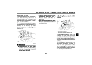
67. Install the plug into the check
hose, and then install the clamp.
CAUTION:
ECA10480
�
Make sure that the air filter ele-
ment is properly seated in the
air filter case.
�
The engine should never be op-
erated without the air filter ele-
ment installed, otherwise the
piston(s) and/or cylinder(s) maybecome excessively worn.
8. Install the air filter case cover by in-
stalling the screws.
9. Connect the hose.10. Install the air filter case by inserting
the projection into the grommet, in-
stalling the bolts, then tightening
the clamp screw.
EAU21280
Adjusting the carburetor The carburetor is an important part of
the engine and requires very sophisti-
cated adjustment. Therefore, most car-
buretor adjustments should be left to a
Yamaha dealer, who has the neces-
sary professional knowledge and expe-
rience. The adjustment described in the
following section, however, may be ser-
viced by the owner as part of routine
maintenance.CAUTION:
ECA10550
The carburetor has been set and ex-
tensively tested at the Yamaha fac-
tory. Changing these settings
without sufficient technical knowl-
edge may result in poor perfor-mance of or damage to the engine.
1. Air filter check hose plug
2. Clamp
3. Air filter check hose
1. Projection
2. Grommet
3. Hose
5KRE2.book Page 11 Monday, June 23, 2003 3:32 PM
Page 45 of 82

PERIODIC MAINTENANCE AND MINOR REPAIR
6-12
6
EAU21340
Adjusting the engine idling
speed The engine idling speed must be
checked and, if necessary, adjusted as
follows at the intervals specified in the
periodic maintenance and lubrication
chart.
The engine should be warm before
making this adjustment.NOTE:�
The engine is warm when it quickly
responds to the throttle.
�
A diagnostic tachometer is neededto make this adjustment.
1. Attach the tachometer to the spark
plug lead.
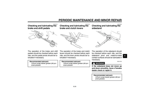
2. Check the engine idling speed
and, if necessary, adjust it to spec-
ification by turning the throttle stop
screw. To increase the engine
idling speed, turn the screw in di-
rection (a). To decrease the en-
gine idling speed, turn the screw in
direction (b).
NOTE:
If the specified idling speed cannot be
obtained as described above, have aYamaha dealer make the adjustment.
EAU21380
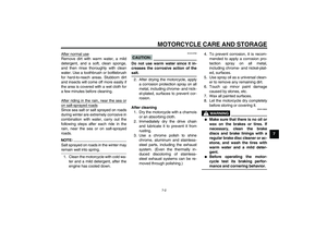
Adjusting the throttle cable
free play The throttle cable free play should mea-
sure 3.0–5.0 mm (0.12–0.20 in) at the
throttle grip. Periodically check the
throttle cable free play and, if neces-
sary, have a Yamaha dealer adjust it.
1. Throttle stop screw
Engine idling speed:
1200–1400 r/min
1. Throttle cable free play
5KRE2.book Page 12 Monday, June 23, 2003 3:32 PM
Page 46 of 82

PERIODIC MAINTENANCE AND MINOR REPAIR
6-13
6
EAU21400
Adjusting the valve clearance The valve clearance changes with use,
resulting in improper air-fuel mixture
and/or engine noise. To prevent this
from occurring, the valve clearance
must be adjusted by a Yamaha dealer
at the intervals specified in the periodic
maintenance and lubrication chart.
EAU21540
Tires To maximize the performance, durabil-
ity, and safe operation of your motor-
cycle, note the following points
regarding the specified tires.
Tire air pressure
The tire air pressure should be checked
and, if necessary, adjusted before each
ride.
WARNING
EWA10500
�
The tire air pressure must be
checked and adjusted on cold
tires (i.e., when the temperature
of the tires equals the ambient
temperature).
�
The tire air pressure must be ad-
justed in accordance with the
riding speed and with the total
weight of rider, passenger, car-
go, and accessories approvedfor this model.
WARNING
EWA11020
Because loading has an enormous
impact on the handling, braking,
performance and safety characteris-
tics of your motorcycle, you should
keep the following precautions in
mind.�
NEVER OVERLOAD THE
MOTORCYCLE! Operation of an
overloaded motorcycle may re-
sult in tire damage, loss of con-
trol, or severe injury. Make sure
that the total weight of rider,Tire air pressure (measured on cold
tires):
0–90 kg (0–198 lb):
Front:
175 kPa (25 psi) (1.75 kgf/cm²)
Rear:
200 kPa (29 psi) (2.00 kgf/cm²)
90–180 kg (198–397 lb):
Front:
225 kPa (33 psi) (2.25 kgf/cm²)
Rear:
225 kPa (33 psi) (2.25 kgf/cm²)
Maximum load*:
180 kg (397 lb)
* Total weight of rider, passenger, car-
go and accessories
5KRE2.book Page 13 Monday, June 23, 2003 3:32 PM
Page 47 of 82

PERIODIC MAINTENANCE AND MINOR REPAIR
6-14
6 passenger, cargo, and accesso-
ries does not exceed the speci-
fied maximum load for the
vehicle.
�
Do not carry along loosely
packed items, which can shift
during a ride.
�
Securely pack the heaviest
items close to the center of the
motorcycle and distribute the
weight evenly on both sides.
�
Adjust the suspension and tire
air pressure with regard to the
load.
�
Check the tire condition and airpressure before each ride.Tire inspection
The tires must be checked before each
ride. If the center tread depth reaches
the specified limit, if the tire has a nail or
glass fragments in it, or if the sidewall is
cracked, have a Yamaha dealer re-
place the tire immediately.
NOTE:The tire tread depth limits may differ
from country to country. Always complywith the local regulations.Tire information
This motorcycle is equipped with tube
tires.
WARNING
EWA10460
�
The front and rear tires should
be of the same make and de-
sign, otherwise the handling
characteristics of the vehicle
cannot be guaranteed.
�
After extensive tests, only the
tires listed below have been ap-
proved for this model byYamaha Motor Co., Ltd.
1. Tire sidewall
2. Tire tread depth
Minimum tire tread depth (front and
rear):
1.6 mm (0.06 in)
Front tire:
Size:
80/100-18M/C 47P
Manufacturer/model:
CHENG SHIN/C-916
IRC/MARBELLA NF27
Rear tire:
Size:
130/90-15M/C 66P
Manufacturer/model:
CHENG SHIN/C-915
IRC/MARBELLA NR31
5KRE2.book Page 14 Monday, June 23, 2003 3:32 PM
Page 48 of 82

PERIODIC MAINTENANCE AND MINOR REPAIR
6-15
6
WARNING
EWA10570
�
Have a Yamaha dealer replace
excessively worn tires. Besides
being illegal, operating the
motorcycle with excessively
worn tires decreases riding sta-
bility and can lead to loss of
control.
�
The replacement of all wheel-
and brake-related parts, includ-
ing the tires, should be left to a
Yamaha dealer, who has the
necessary professional knowl-
edge and experience.
�
It is not recommended to patch
a punctured tube. If unavoid-
able, however, patch the tube
very carefully and replace it as
soon as possible with a high-quality product.
EAU21940
Spoke wheels To maximize the performance, durabil-
ity, and safe operation of your motor-
cycle, note the following points
regarding the specified wheels.�
The wheel rims should be checked
for cracks, bends or warpage, and
the spokes for looseness or dam-
age before each ride. If any dam-
age is found, have a Yamaha
dealer replace the wheel. Do not
attempt even the smallest repair to
the wheel. A deformed or cracked
wheel must be replaced.
�
The wheel should be balanced
whenever either the tire or wheel
has been changed or replaced. An
unbalanced wheel can result in
poor performance, adverse han-
dling characteristics, and a short-
ened tire life.
�
Ride at moderate speeds after
changing a tire since the tire sur-
face must first be “broken in” for it
to develop its optimal characteris-
tics.
EAU22040
Adjusting the clutch lever free
play The clutch lever free play should mea-
sure 5.0–10.0 mm (0.20–0.39 in) as
shown. Periodically check the clutch le-
ver free play and, if necessary, adjust it
as follows.
1. Loosen the locknut at the clutch le-
ver.
2. To increase the clutch lever free
play, turn the adjusting bolt in di-
rection (a). To decrease the clutch
lever free play, turn the adjusting
bolt in direction (b).1. Locknut
2. Clutch lever free play adjusting bolt
3. Clutch lever free play
5KRE2.book Page 15 Monday, June 23, 2003 3:32 PM