Page 17 of 82

INSTRUMENT AND CONTROL FUNCTIONS
3-3
3
EAU11630
Speedometer unit The speedometer unit is equipped with
a speedometer, an odometer and a
tripmeter. The speedometer shows
riding speed. The odometer shows the
total distance traveled. The tripmeter
shows the distance traveled since it
was last set to zero with the reset knob.
The tripmeter can be used to estimate
the distance that can be traveled with a
full tank of fuel. This information will en-
able you to plan future fuel stops.
EAU12090
Self-diagnosis device This model is equipped with a self-diag-
nosis device for various electrical cir-
cuits.
If any of those circuits are defective, the
engine trouble warning light will come
on or flash. If this occurs, have a
Yamaha dealer check the vehicle.CAUTION:
ECA11170
To prevent engine damage, be sure
to consult a Yamaha dealer as soonas possible if this occurs.
EAU12330
Anti-theft alarm (optional) This model can be equipped with an
optional anti-theft alarm by a Yamaha
dealer. Contact a Yamaha dealer for
more information.
1. Speedometer
2. Odometer
3. Tripmeter
4. Tripmeter reset knob
5KRE2.book Page 3 Monday, June 23, 2003 3:32 PM
Page 18 of 82

INSTRUMENT AND CONTROL FUNCTIONS
3-4
3
EAU12342
Handlebar switches LeftRight
EAU12350
Pass switch “”
Press this switch to flash the headlight.
EAU12400
Dimmer switch “/”
Set this switch to “” for the high
beam and to “” for the low beam.
EAU12460
Turn signal switch “/”
To signal a right-hand turn, push this
switch to “”. To signal a left-hand
turn, push this switch to “”. When re-
leased, the switch returns to the centerposition. To cancel the turn signal
lights, push the switch in after it has re-
turned to the center position.
EAU12500
Horn switch “”
Press this switch to sound the horn.
EAU12590
Light switch “//”
Set this switch to “” to turn on the
auxiliary light, meter lighting and tail-
light. Set the switch to “” to turn on
the headlight also. Set the switch to “”
to turn off all the lights.
EAU12660
Engine stop switch “/”
Set this switch to “” before starting
the engine. Set this switch to “” to
stop the engine in case of an emergen-
cy, such as when the vehicle overturns
or when the throttle cable is stuck.
EAU12710
Start switch “”
Push this switch to crank the engine
with the starter.
1. Pass switch “”
2. Dimmer switch “/”
3. Turn signal switch “/”
4. Horn switch “”
1. Engine stop switch “/”
2. Light switch “//”
3. Start switch “”
5KRE2.book Page 4 Monday, June 23, 2003 3:32 PM
Page 19 of 82
INSTRUMENT AND CONTROL FUNCTIONS
3-5
3
CAUTION:
ECA10050
See page 5-1 for starting instruc-tions prior to starting the engine.
EAU12820
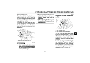
Clutch lever The clutch lever is located at the left
handlebar grip. To disengage the
clutch, pull the lever toward the handle-
bar grip. To engage the clutch, release
the lever. The lever should be pulled
rapidly and released slowly for smooth
clutch operation.
The clutch lever is equipped with a
clutch switch, which is part of the igni-
tion circuit cut-off system. (See page
3-11.)
EAU12870
Shift pedal The shift pedal is located on the left
side of the engine and is used in com-
bination with the clutch lever when
shifting the gears of the 5-speed con-
stant-mesh transmission equipped on
this motorcycle.
1. Clutch lever
1. Shift pedal
5KRE2.book Page 5 Monday, June 23, 2003 3:32 PM
Page 20 of 82
INSTRUMENT AND CONTROL FUNCTIONS
3-6
3
EAU12890
Brake lever The brake lever is located at the right
handlebar grip. To apply the front
brake, pull the lever toward the handle-
bar grip.
EAU12941
Brake pedal The brake pedal is on the right side of
the motorcycle. To apply the rear
brake, press down on the brake pedal.
EAU13000
Fuel tank cap To remove the fuel tank cap
Insert the key into the lock and turn it
1/4 turn clockwise. The lock will be re-
leased and the fuel tank cap can be re-
moved.
To install the fuel tank cap
1. Push the fuel tank cap into position
with the key inserted in the lock.
2. Turn the key counterclockwise to
the original position, and then re-
move it.
1. Brake lever
1. Brake pedal
1. Unlock.
5KRE2.book Page 6 Monday, June 23, 2003 3:32 PM
Page 21 of 82

INSTRUMENT AND CONTROL FUNCTIONS
3-7
3
NOTE:The fuel tank cap cannot be installed
unless the key is in the lock. In addition,
the key cannot be removed if the cap isnot properly installed and locked.
WARNING
EWA11140
Make sure that the fuel tank cap isproperly installed before riding.
EAU13210
Fuel Make sure that there is sufficient fuel in
the tank. Fill the fuel tank to the bottom
of the filler tube as shown.
WARNING
EWA10880
�
Do not overfill the fuel tank, oth-
erwise it may overflow when the
fuel warms up and expands.
�
Avoid spilling fuel on the hot en-gine.
CAUTION:
ECA10070
Immediately wipe off spilled fuel
with a clean, dry, soft cloth, since
fuel may deteriorate painted surfac-es or plastic parts.
EAU13320
CAUTION:
ECA11400
Use only unleaded gasoline. The use
of leaded gasoline will cause severe
damage to internal engine parts,
such as the valves and piston rings,as well as to the exhaust system.
Your Yamaha engine has been de-
signed to use regular unleaded gaso-
line with a research octane number of
91 or higher. If knocking (or pinging) oc-
curs, use a gasoline of a different brand
1. Fuel tank filler tube
2. Fuel level
Recommended fuel:
REGULAR UNLEADED GASOLINE
ONLY
Fuel tank capacity:
11.0 L (2.91 US gal) (2.42 Imp.gal)
Fuel reserve amount:
3.4 L (0.90 US gal) (0.75 Imp.gal)
5KRE2.book Page 7 Monday, June 23, 2003 3:32 PM
Page 22 of 82

INSTRUMENT AND CONTROL FUNCTIONS
3-8
3or premium unleaded fuel. Use of un-
leaded fuel will extend spark plug life
and reduce maintenance costs.
EAU13580
Fuel cock This model is equipped with a negative
pressure fuel cock. The fuel cock sup-
plies fuel from the tank to the carburetor
while also filtering it.
The fuel cock lever positions are ex-
plained as follows and shown in the il-
lustrations.
ON
With the fuel cock lever in this position,
fuel flows to the carburetor when the
engine is running. Turn the fuel cock le-
ver to this position when starting the en-
gine and riding.RES
This indicates reserve. With the fuel
cock lever in this position, the fuel re-
serve is made available. Quickly turn
the fuel cock lever to this position if you
run out of fuel while riding, otherwise
the engine may stall and will have to be
primed (see “PRI”). After turning the
fuel cock lever to “RES”, refuel as soon
as possible and be sure to turn the fuel
cock lever back to “ON”!1. Pointed end positioned over “ON”
1. Pointed end positioned over “RES”
5KRE2.book Page 8 Monday, June 23, 2003 3:32 PM
Page 23 of 82

INSTRUMENT AND CONTROL FUNCTIONS
3-9
3 PRI
This indicates prime. With the fuel cock
lever in this position, the engine can be
“primed”. Turn the fuel cock lever to this
position when the engine has been al-
lowed to run out of fuel. This sends fuel
directly to the carburetor, which will
make starting easier. After the engine
has started, be sure to turn the lever to
“ON” (or “RES” if you have not refueled
yet).
EAU13590
Starter (choke) lever “” Starting a cold engine requires a richer
air-fuel mixture, which is supplied by
the starter (choke).
Move the lever in direction (a) to turn on
the starter (choke).
Move the lever in direction (b) to turn off
the starter (choke).
EAU14281
Helmet holder To open the helmet holder, insert the
key into the lock, and then turn the key
as shown.
To lock the helmet holder, place it in the
original position, and then remove the
key.
WARNING
EWA10160
Never ride with a helmet attached to
the helmet holder, since the helmet
may hit objects, causing loss of con-trol and possibly an accident.
1. Pointed end positioned over “PRI”
1. Starter (choke) lever “”
1. Helmet holder
2. Unlock.
5KRE2.book Page 9 Monday, June 23, 2003 3:32 PM
Page 24 of 82

INSTRUMENT AND CONTROL FUNCTIONS
3-10
3
EAU14880
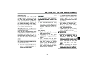
Adjusting the shock absorber
assemblies Each shock absorber assembly is
equipped with a spring preload adjust-
ing ring.CAUTION:
ECA10100
Never attempt to turn an adjusting
mechanism beyond the maximum orminimum settings.
WARNING
EWA10210
Always adjust both shock absorber
assemblies equally, otherwise poor
handling and loss of stability mayresult.
Adjust the spring preload as follows.
To increase the spring preload and
thereby harden the suspension, turn
the adjusting ring on each shock ab-
sorber assembly in direction (a). To de-
crease the spring preload and thereby
soften the suspension, turn the adjust-
ing ring on each shock absorber as-
sembly in direction (b).NOTE:Align the appropriate notch in the ad-
justing ring with the position indicatoron the shock absorber.
EAU15300
Sidestand The sidestand is located on the left side
of the frame. Raise the sidestand or
lower it with your foot while holding the
vehicle upright.NOTE:The built-in sidestand switch is part of
the ignition circuit cut-off system, which
cuts the ignition in certain situations.
(See further down for an explanation ofthe ignition circuit cut-off system.)
WARNING
EWA10240
The vehicle must not be ridden with
the sidestand down, or if the side-
stand cannot be properly moved up
(or does not stay up), otherwise the
sidestand could contact the ground
and distract the operator, resulting
in a possible loss of control.
Yamaha’s ignition circuit cut-off
system has been designed to assist
the operator in fulfilling the respon-
sibility of raising the sidestand be-
fore starting off. Therefore, check
this system regularly as described
1. Spring preload adjusting ring
2. Position indicator
Spring preload setting:
Minimum (soft):
1
Standard:
2
Maximum (hard):
5
5KRE2.book Page 10 Monday, June 23, 2003 3:32 PM