Page 625 of 754
 5 - 60
CHAS
AMORTISSEUR ARRIERE
FEDERBEIN
AMORTIGUADOR TRASERO
FEDERBEIN
Demontage-Arbeiten:1 Federbein demontieren2 Federbein zerlegen
Demontage-ArbeitenReihen-
folgeBauteil Anz. Bemerkungen
Vorberei")
5 - 60
CHAS
AMORTISSEUR ARRIERE
FEDERBEIN
AMORTIGUADOR TRASERO
FEDERBEIN
Demontage-Arbeiten:1 Federbein demontieren2 Federbein zerlegen
Demontage-ArbeitenReihen-
folgeBauteil Anz. Bemerkungen
Vorbereitung für den AusbauFEDERBEIN DEMONTIEREN
Das Motorrad am Motor aufbocken.
WARNUNGDas Motorrad gegen Umfallen sichern.
Sitz, Paßband und Seitendeckel Siehe Abschnitt “SITZBANK, KRAFTSTOFFTANK
UND SEITENABDECKUNGEN” in KAPITEL 4.
Luftfilterdeckel Siehe Abschnitt “LUFTFILTER REINGEN” in KAPI-
TEL 3.
Schalldämpfer Siehe Abschnitt “AUSPUFF UND SCHALLDÄMP-
FER” in KAPITEL 4.
Kühlflüssigkeit ablassen. Siehe Abschnitt “KÜHLFLÜSSIGKEIT WECHSELN”
in KAPITEL 3.
Kühlmittelausgleichsbehälter-Lüftungs-
schlauchAn der Kühlmittelbehältertank-Seite abtrennen.
Kühlmittelausgleichsbehälter-Schlauch An der Kühlmittelbehältertank-Seite abtrennen.
Batterie Siehe Abschnitt “BATTERIE KONTROLLIEREN UND
LADEN” in KAPITEL 3.
AMORTISSEUR ARRIERE
Organisation de la dépose:1 Dépose de l’amortisseur arrière2 Démontage de l’amortisseur arrière
Organisation de la dépose Ordre Nom de pièce QtéRemarques
Préparation pour la déposeDEPOSE DE L’AMORTISSEUR
ARRIERE
Maintenir la machine en plaçant un support
approprié sous le moteur.
AVERTISSEMENT
Bien soutenir la machine afin qu’elle ne risque pas dese renverser.
Siège, bande de gonflage et couvercles latéraux Se référer à la section “SELLE, RESERVOIR A
ESSENCE ET CACHES LATERAUX” du CHAPITRE 4.
Couvercle de filtre à air Se référer à la section “NETTOYAGE DU FILTRE A
AIR” du CHAPITRE 3.
Silencieux Se référer à la section “TUYAU D'ECHAPPEMENT ET
SILENCIEUX” du CHAPITRE 4.
Vidanger le liquide de refroidissement. Se référer à la section “REMPLACEMENT DU
LIQUIDE DE REFROIDISSEMENT” du CHAPITRE 3.
Flexible de reniflard du réservoir de liquide de
refroidissementDébrancher du côté du réservoir du liquide de refroidisse-
ment.
Flexible de réservoir de liquide de refroidisse-
mentDébrancher du côté du réservoir du liquide de refroidisse-
ment.
Batterie Se référer à la section “CONTRÔLE ET RECHARGE DE
LA BATTERIE” du CHAPITRE 3.
AMORTIGUADOR TRASERO
Alcance de la extracción:1 Extracción del amortiguador trasero2 Desmontaje del amortiguador trasero
Alcance de la extracción Orden Denominación de la pieza Cantidad Observaciones
Preparación para la extracciónEXTRACCIÓN DEL AMORTIGUADOR
TRASERO
Sujete el vehículo colocando una base apro-
piada debajo del motor.
ADVERTENCIASujete firmemente el vehículo de forma que no hayariesgo de que se caiga.
Asiento, banda de ajuste y cubiertas lateralesConsulte el apartado “ASIENTO, DEPÓSITO DE COM-
BUSTIBLE Y CUBIERTAS LATERALES” del CAPÍ-
TULO 4.
Cubierta del filtro de aireConsulte el apartado “LIMPIEZA DEL FILTRO DE
AIRE” del CAPÍTULO 3.
Silenciador Consulte el apartado “TUBO DE ESCAPE Y SILENCIA-
DOR” del CAPÍTULO 4.
Drene el refrigerante. Consulte el apartado “SUSTITUCIÓN DEL REFRIGE-
RANTE” del CAPÍTULO 3.
Tubo respiradero del depósito de refrigerante Desconecte en el lado del depósito de refrigerante.
Tubo del depósito de refrigerante Desconecte en el lado del depósito de refrigerante.
Batería Consulte el apartado “INSPECCIÓN Y CARGA DE LA
BATERÍA” del CAPÍTULO 3.
Page 626 of 754
5 - 61
CHASREAR SHOCK ABSORBER
Extent of removal Order Part name Q’ty Remarks
Disconnect the starter relay cou-
pler.
Starter motor lead Disconnect at the starter relay side.
1 Locking tie 2
2 Taillight coupler 1
3 Starting circuit cut-off relay cou-
pler1
4 Plastic band 2
5 Clamp (air filter joint) 1 Only loosening.
6 Rear frame 1
7 Bolt (rear shock absorber-relay
arm)1 Hold the swingarm.
8 Bolt (rear shock absorber-frame) 1
9 Rear shock absorber 1
10 Locknut 1 Only loosening.
11 Adjuster 1 Only loosening.
12 Spring guide (lower) 1
13 Spring guide (upper) 1
2
1
Page 628 of 754
5 - 62
CHASREAR SHOCK ABSORBER
Extent of removal Order Part name Q’ty Remarks
14 Spring (rear shock absorber) 1
15 Bearing 2 Refer to “REMOVAL POINTS”.
2
Page 630 of 754
 5 - 63
CHAS
EC586000
HANDLING NOTE
WARNING
This shock absorber is provided with a
separate type tank filled with high-pressure
nitrogen gas. To prevent the danger of
explosion, read and understand the")
5 - 63
CHAS
EC586000
HANDLING NOTE
WARNING
This shock absorber is provided with a
separate type tank filled with high-pressure
nitrogen gas. To prevent the danger of
explosion, read and understand the follow-
ing information before handling the shock
absorber.
The manufacturer can not be held respon-
sible for property damage or personal
injury that may result from improper han-
dling.
1. Never tamper or attempt to disassem-
ble the cylinder or the tank.
2. Never throw the shock absorber into
an open flame or other high heat. The
shock absorber may explode as a
result of nitrogen gas expansion and/
or damage to the hose.
3. Be careful not to damage any part of
the gas tank. A damaged gas tank will
impair the damping performance or
cause a malfunction.
4. Take care not to scratch the contact
surface of the piston rod with the cylin-
der; or oil could leak out.
5. Never attempt to remove the plug at
the bottom of the nitrogen gas tank. It
is very dangerous to remove the plug.
6. When scrapping the shock absorber,
follow the instructions on disposal.
EC587000
NOTES ON DISPOSAL (YAMAHA DEALERS
ONLY)
Before disposing the shock absorber, be sure
to extract the nitrogen gas from valve 1. Wear
eye protection to prevent eye damage from
escaping gas and/or metal chips.
WARNING
To dispose of a damaged or worn-out
shock absorber, take the unit to your
Yamaha dealer for this disposal procedure.
REAR SHOCK ABSORBER
Page 632 of 754
5 - 64
CHAS
EC583000
REMOVAL POINTS
EC583320
Bearing
1. Remove:
�Stopper ring (upper bearing) 1
NOTE:
Press in the bearing while pressing its outer
race and remove the stopper ring.
2. Remove:
�Upper bearing 1
NOTE:
Remove the bearing by pressing its outer race.
3. Remove:
�Lower bearing 1
NOTE:
Remove the bearing by pressing its outer race.
EC584000
INSPECTION
Rear shock absorber
1. Inspect:
�Damper rod 1
Bends/damage → Replace absorber
assembly.
�Shock absorber 2
Oil leaks → Replace absorber assem-
bly.
Gas leaks → Replace absorber assem-
bly.
�Spring 3
Damage → Replace spring.
Fatigue → Replace spring.
Move spring up and down.
�Spring guide 4
Wear/damage → Replace spring guide.
�Bearing 5
Free play exists/unsmooth revolution/
rust → Replace.
REAR SHOCK ABSORBER
Page 634 of 754
5 - 65
CHASREAR SHOCK ABSORBER
EC585000
ASSEMBLY AND INSTALLATION
EC585300
Bearing
1. Install:
�Upper bearing 1
NOTE:
Install the bearing parallel until the stopper ring
groove appears by pressing its outer race.
CAUTION:
Do not apply the grease on the bearing
outer race because it will wear the rear
shock absorber surface on which the bear-
ing is press fitted.
2. Install:
�Stopper ring (upper bearing) 1
NOTE:
After installing the stopper ring, push back the
bearing until it contacts the stopper ring.
New
3. Install:
�Lower bearing 1
NOTE:
Install the bearing by pressing it on the side
having the manufacture’s marks or numbers.
Installed depth of the bearing a:
4 mm (0.16 in)
EC585111
Spring (rear shock absorber)
1. Install:
�Spring 1
�Spring guide (upper) 2
�Spring guide (lower) 3
Page 636 of 754
5 - 66
CHASREAR SHOCK ABSORBER
2. Tighten:
�Adjuster 1
3. Adjust:
�Spring length (installed) a
* For EUROPE, AUS, NZ and ZA
NOTE:
The length of the spring (installed) changes
1.5 mm (0.06 in) per turn of the adjuster.
CAUTION:
Never attempt to turn the adjuster beyond
the maximum or minimum setting.
Spring length (installed) a:
Standard
lengthExtent of
adjustment
245 mm (9.65 in)
* 247 mm (9.72 in)240.5 ~ 258.5 mm
(9.47 ~ 10.18 in)
4. Tighten:
�Locknut 1
Rear shock absorber
1. Install:
�Dust seal 1
�O-ring 2
�Collar 3
NOTE:
�Apply the molybdenum disulfide grease on
the bearing.
�Apply the lithium soap base grease on the
dust seals, O-rings and collars.
New
Page 638 of 754
5 - 67
CHASREAR SHOCK ABSORBER
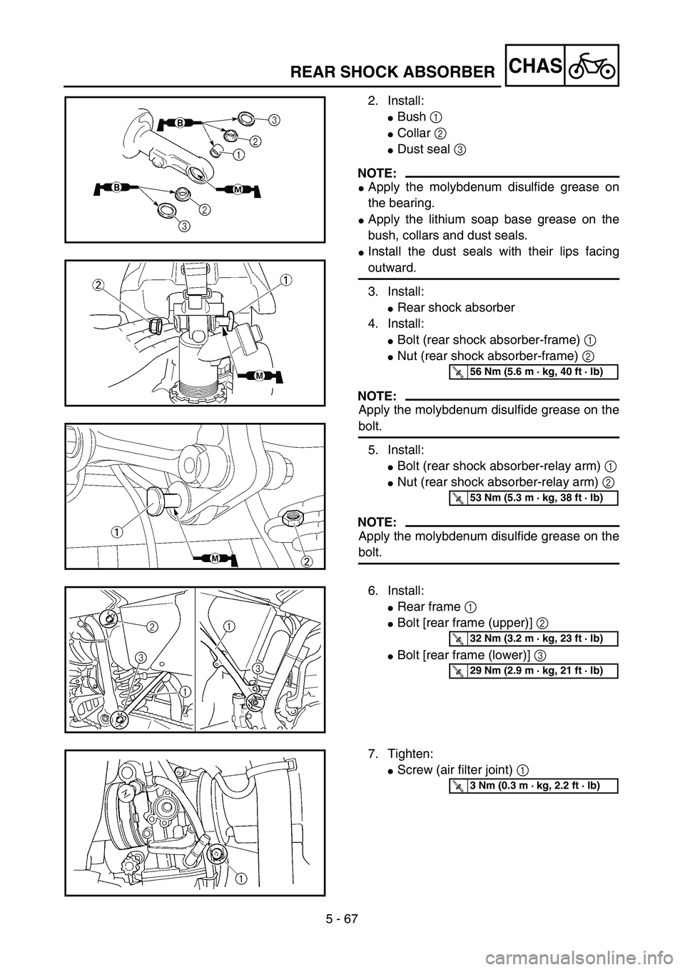
2. Install:
�Bush 1
�Collar 2
�Dust seal 3
NOTE:
�Apply the molybdenum disulfide grease on
the bearing.
�Apply the lithium soap base grease on the
bush, collars and dust seals.
�Install the dust seals with their lips facing
outward.
3. Install:
�Rear shock absorber
4. Install:
�Bolt (rear shock absorber-frame) 1
�Nut (rear shock absorber-frame) 2
NOTE:
Apply the molybdenum disulfide grease on the
bolt.
5. Install:
�Bolt (rear shock absorber-relay arm) 1
�Nut (rear shock absorber-relay arm) 2
NOTE:
Apply the molybdenum disulfide grease on the
bolt.
T R..56 Nm (5.6 m · kg, 40 ft · lb)
T R..53 Nm (5.3 m · kg, 38 ft · lb)
6. Install:
�Rear frame 1
�Bolt [rear frame (upper)] 2
�Bolt [rear frame (lower)] 3
T R..32 Nm (3.2 m · kg, 23 ft · lb)
T R..29 Nm (2.9 m · kg, 21 ft · lb)
7. Tighten:
�Screw (air filter joint) 1
T R..3 Nm (0.3 m · kg, 2.2 ft · lb)
 5 - 61
CHASREAR SHOCK ABSORBER
Extent of removal Order Part name Q’ty Remarks
Disconnect the starter relay cou-
pler.
Starter motor lead Disconnect at the starter relay side.
1 Locking tie 2
2 Taill")
 5 - 62
CHASREAR SHOCK ABSORBER
Extent of removal Order Part name Q’ty Remarks
14 Spring (rear shock absorber) 1
15 Bearing 2 Refer to “REMOVAL POINTS”.
2")