Page 618 of 754
5 - 57
CHASSWINGARM
3. Install:
�Collar 1
To connecting rod 2.
NOTE:
Apply the molybdenum disulfide grease on the
collar and oil seal lips.
4. Install:
�Connecting rod 1
�Bolt (connecting rod) 2
�Plain washer 3
�Nut (connecting rod) 4
To relay arm 5.
NOTE:
Apply the molybdenum disulfide grease on the
bolt.
T R..80 Nm (8.0 m · kg, 58 ft · lb)
5. Install:
�Relay arm 1
�Bolt (relay arm) 2
�Plain washer 3
�Nut (relay arm) 4
To swingarm.
NOTE:
�Apply the molybdenum disulfide grease on
the bolt.
�Do not tighten the nut yet.
6. Install:
�Swingarm 1
�Pivot shaft 2
NOTE:
�Apply the molybdenum disulfide grease on
the pivot shaft.
�Insert the pivot shaft from right side.
T R..85 Nm (8.5 m · kg, 61 ft · lb)
7. Check:
�Swingarm side play a
Free play exists → Replace thrust bear-
ing.
�Swingarm up and down movement b
Unsmooth movement/binding/rough
spots → Grease or replace bearings,
bushes and collars.
Page 620 of 754
5 - 58
CHASSWINGARM
8. Install:
�Bolt (connecting rod) 1
�Plain washer 2
�Nut (connecting rod) 3
NOTE:
�Apply the molybdenum disulfide grease on
the bolt.
�Do not tighten the nut yet.
9. Install:
�Bolt (rear shock absorber-relay arm) 1
�Nut (rear shock absorber-relay arm) 2
NOTE:
Apply the molybdenum disulfide grease on the
bolt.
T R..53 Nm (5.3 m · kg, 38 ft · lb)
10. Tighten:
�Nut (connecting rod) 1
T R..80 Nm (8.0 m · kg, 58 ft · lb)
11. Tighten:
�Nut (relay arm) 1
T R..80 Nm (8.0 m · kg, 58 ft · lb)
12. Install:
�Cap 1
NOTE:
Install the cap (right) with its mark a facing
forward.
Page 626 of 754
5 - 61
CHASREAR SHOCK ABSORBER
Extent of removal Order Part name Q’ty Remarks
Disconnect the starter relay cou-
pler.
Starter motor lead Disconnect at the starter relay side.
1 Locking tie 2
2 Taillight coupler 1
3 Starting circuit cut-off relay cou-
pler1
4 Plastic band 2
5 Clamp (air filter joint) 1 Only loosening.
6 Rear frame 1
7 Bolt (rear shock absorber-relay
arm)1 Hold the swingarm.
8 Bolt (rear shock absorber-frame) 1
9 Rear shock absorber 1
10 Locknut 1 Only loosening.
11 Adjuster 1 Only loosening.
12 Spring guide (lower) 1
13 Spring guide (upper) 1
2
1
Page 638 of 754
5 - 67
CHASREAR SHOCK ABSORBER
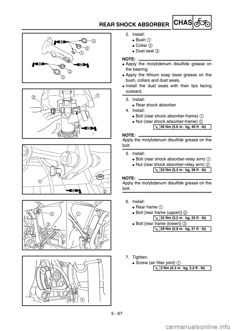
2. Install:
�Bush 1
�Collar 2
�Dust seal 3
NOTE:
�Apply the molybdenum disulfide grease on
the bearing.
�Apply the lithium soap base grease on the
bush, collars and dust seals.
�Install the dust seals with their lips facing
outward.
3. Install:
�Rear shock absorber
4. Install:
�Bolt (rear shock absorber-frame) 1
�Nut (rear shock absorber-frame) 2
NOTE:
Apply the molybdenum disulfide grease on the
bolt.
5. Install:
�Bolt (rear shock absorber-relay arm) 1
�Nut (rear shock absorber-relay arm) 2
NOTE:
Apply the molybdenum disulfide grease on the
bolt.
T R..56 Nm (5.6 m · kg, 40 ft · lb)
T R..53 Nm (5.3 m · kg, 38 ft · lb)
6. Install:
�Rear frame 1
�Bolt [rear frame (upper)] 2
�Bolt [rear frame (lower)] 3
T R..32 Nm (3.2 m · kg, 23 ft · lb)
T R..29 Nm (2.9 m · kg, 21 ft · lb)
7. Tighten:
�Screw (air filter joint) 1
T R..3 Nm (0.3 m · kg, 2.2 ft · lb)
Page 640 of 754
5 - 68
CHAS
8. Install:
�Plastic band 1
�Starting circuit cut-off relay coupler 2
�Taillight coupler 3
�Locking tie 4
3
2
1
4
REAR SHOCK ABSORBER
Page 642 of 754

6 - 1
–+ELEC
ELECTRICAL COMPONENTS AND WIRING DIAGRAM
EC600000
ELECTRICAL
EC610000
ELECTRICAL COMPONENTS AND WIRING DIAGRAM
EC611000
ELECTRICAL COMPONENTS
1
Headlight
2
“ENGINE ST")
6 - 1
–+ELEC
ELECTRICAL COMPONENTS AND WIRING DIAGRAM
EC600000
ELECTRICAL
EC610000
ELECTRICAL COMPONENTS AND WIRING DIAGRAM
EC611000
ELECTRICAL COMPONENTS
1
Headlight
2
“ENGINE STOP”
button
3
Clutch switch
4
Diode
5
Starter relay diode
6
TPS (throttle posi-
tion sensor)
7
Starter relay
8
Fuse
9
Starting circuit
cut-off relay
0
Taillight
A
Neutral switch
B
Starter motor
C
AC magneto
D
Rectifier/regulator
E
Ignition coil
F
Spark plug
G
Start switch
H
Main switch
I
CDI unit
J
Battery
COLOR CODE
B.......................Black
Br .....................Brown
Gy ....................Gray
L .......................Blue
O ......................Orange
R ......................Red
Sb.....................Sky blue
W......................White
Y.......................Yellow
B/L....................Black/Blue
EC612000
WIRING DIAGRAM
1 2345
678
90
A B
CDEFGH
I
J
WR
WR
R
BR/BBr
R
BR/BBr
RW
L/RL/BBB
SbL/W
WY
YW
L/YBBB
WY
RYW
R
LY
B
YLB/L
B
B
ON
OFF
10A
BB
OFF
STARTSTART
R-BrL/W
B
BrL/W
BrL/W
L/B
-YB
YL
B
L-B
L/WSb
B/WBBB
W/RB/W
R/BGyBrL/W
ON
STOP
OB
LYSbB/L
W RBrB/W
L/BGyWR/B
B O
L/YSbL/R
R W
Y W
Y W
Y
L B
B
B
RRR/B
B Br B
B B B B
L/W
R
R
R R B
R
BrBr
L/W L/W
Br B
L/B
L/B
L/R
Br
R/B
L/B L/W
B/W
W W/RW
RO
L
Y
B/L
O
B
L
Y
B/LSbL/WB/W
B
L/R L/Y L/Y
B
SbSbL/W
BGy
SbBB/LYO
L
*2
O B
L YL/W
B/L
*1
CD
BI
5
9
G3 4
A 2J
EF
6 7
K8
1
0
*
2
*1
*2: Except for USA
*1: For USA
B/W .................. Black/White
L/B ................... Blue/Black
L/R ................... Blue/Red
L/Y ................... Blue/Yellow
L/W .................. Blue/White
R/B................... Red/Black
Page 658 of 754
 6 - 7
–+ELEC
ELECTRIC STARTING SYSTEM
STARTING CIRCUIT CUT-OFF SYSTEM
OPERATION
If the main switch is set to “ON”, the starter
motor can only operate if at least one of the
following conditions")
6 - 7
–+ELEC
ELECTRIC STARTING SYSTEM
STARTING CIRCUIT CUT-OFF SYSTEM
OPERATION
If the main switch is set to “ON”, the starter
motor can only operate if at least one of the
following conditions is met:
�The transmission is in neutral (the neutral
switch is closed).
�The clutch lever is pulled to the handlebar
(the clutch switch is closed).
The starting circuit cut-off relay prevents the
starter motor from operating when neither of
these conditions has been met. In this
instance, the starting circuit cut-off relay is
open so current cannot reach the starter
motor. When at least one of the above condi-
tions has been met the starting circuit cut-off
relay is closed and the engine can be started
by pressing the start switch.
WHEN THE TRANSMISSION IS
IN NEUTRAL
WHEN THE CLUTCH LEVER IS
PULLED TO THE HANDLEBAR
1Battery
2Main fuse
3Main switch
4Starting circuit cut-off relay
5Start switch
6Diode
7Clutch switch
8Neutral switch
9Starter relay
0Starter motor
12
M
3
4
5
8 76 9
0
ELECTRIC STARTING SYSTEM
Page 660 of 754
 –+ELEC
6 - 8
ELECTRIC STARTING SYSTEM
INSPECTION STEPS
If the starter motor will not operate, use the following inspection steps.
*1 marked: Refer to “FUSE INSPECTION” section in the CHAPTER 3.")
–+ELEC
6 - 8
ELECTRIC STARTING SYSTEM
INSPECTION STEPS
If the starter motor will not operate, use the following inspection steps.
*1 marked: Refer to “FUSE INSPECTION” section in the CHAPTER 3.
*2 marked: Refer to “BATTERY INSPECTION AND CHARGING” section in the CHAPTER 3.
*3 marked: Refer to “MAIN SWITCH INSPECTION” section.
*4 marked: Refer to “NEUTRAL SWITCH INSPECTION” section.
NOTE:
�Remove the following parts before inspection.
1) Seat
2) Rear fender
�Use 12 V battery in this inspection.
�Use the following special tools in this inspection.
Pocket tester:
YU-3112-C/90890-03112
*1 Check fuseReplace fuse and
check wire harness.
*2 Check battery Recharge or replace.
Check each coupler and
wire connection.Repair or replace.
*3 Check main switch. Replace.
Check starter motor
operation.Repair or replace.
Check starting circuit
cut-off relay.Replace.
Check starter relay. Replace.
*4 Check neutral switch. Replace.
Check clutch switch. Replace.
Check diode. Replace.
Check start switch. Replace.
OK
OK
OK
OK
OK
OK
OK
OK
OK
OK
No good
No good
No good
No good
No good
No good
No good
No good
No good
No good
No good


 5 - 61
CHASREAR SHOCK ABSORBER
Extent of removal Order Part name Q’ty Remarks
Disconnect the starter relay cou-
pler.
Starter motor lead Disconnect at the starter relay side.
1 Locking tie 2
2 Taill")