Page 146 of 364

6. Install:
�Tappet cover (intake side) 1
�O-ring 2
NOTE:
Apply the lithium soap base grease on the O-ring.
7. Install:
�Tappet cover (exhaust side)")
3 - 10
INSP
ADJ
SPARK ARRESTER CLEANING (For USA)
6. Install:
�Tappet cover (intake side) 1
�O-ring 2
NOTE:
Apply the lithium soap base grease on the O-ring.
7. Install:
�Tappet cover (exhaust side)
�O-ring
�Spark plug
�Timing plug
�Crankshaft end cover
NOTE:
Apply the lithium soap base grease on the O-ring.
8. Install:
�Air filter case
�Air scoop (right)
SPARK ARRESTER CLEANING (For USA)
WARNING
�Be sure the exhaust pipe and muffler are
cool before cleaning the spark arrester.
�Do not start the engine when cleaning the
exhaust system.
1. Remove:
�Bolt (tailpipe) 1
2. Remove:
�Tailpipe 2
Pull the tailpipe out of the muffler.
3. Clean:
�Spark arrester
Use a wire brush to remove any carbon
deposits from the spark arrester portion
of the muffler body 3 inner surface.
Tap the tailpipe lightly and remove the
carbon deposits from the outside por-
tion a of the tailpipe.
4. Install:
�Tailpipe
Insert the tailpipe into the muffler and
align the bolt hole.
�Bolt (tailpipe)
T R..18 Nm (1.8 m · kg, 13 ft · lb)
New
T R..18 Nm (1.8 m · kg, 13 ft · lb)
New
T R..13 Nm (1.3 m · kg, 9.4 ft · lb)
T R..7 Nm (0.7 m · kg, 5.1 ft · lb)
T R..7 Nm (0.7 m · kg, 5.1 ft · lb)
2
1
3
a
T R..7 Nm (0.7 m · kg, 5.1 ft · lb)
Page 150 of 364

3 - 12
INSP
ADJ
DRIVE CHAIN SLACK ADJUSTMENT
DRIVE CHAIN SLACK ADJUSTMENT
1. Elevate the rear wheel by placing the
suitable stand under the engine.
2. Check:
�Drive chain slack a
In the center between the drive axle
and rear wheel axle.
Out of specification → Adjust.
NOTE:
Before checking and/or adjusting, rotate the
rear wheel through several revolutions and
check the slack several times to find the tight-
est point. Check and/or adjust chain slack with
rear wheel in this “tight chain” position.
Drive chain slack:
40 ~ 53 mm (1.6 ~ 2.1 in)
3. Adjust:
�Drive chain slack
Drive chain slack adjustment steps:
�Loosen the wheel axle nut 1 and locknuts
2.
�Adjust chain slack by turning the adjusters
3.
To tighten →Turn adjuster 3 clockwise.
To loosen →Turn adjuster 3 counter-
clockwise and push wheel
forward.
�Turn each adjuster exactly the same
amount to maintain correct axle alignment.
(There are marks a on each side of chain
puller alignment.)
NOTE:
Turn the adjuster so that the chain is in line
with the sprocket, as viewed from the rear.
CAUTION:
Too small chain slack will overload the
engine and other vital parts; keep the
slack within the specified limits.
13 a2
Page 152 of 364
3 - 13
INSP
ADJFRONT FORK INSPECTION/REAR SHOCK ABSORBER INSPECTION/
REAR SHOCK ABSORBER SPRING PRELOAD ADJUSTMENT
�Tighten the wheel axle nut while pushing
down the drive chain.
T R..
Axle nut:
60 Nm (6.0 m • kg, 43 ft • lb)
�Tighten the locknuts.
T R..
Locknut:
7 Nm (0.7 m • kg, 5.1 ft • lb)
EC36C000
FRONT FORK INSPECTION
1. Inspect:
�Front fork smooth action
Operate the front brake and stroke the
front fork.
Unsmooth action/oil leakage → Repair
or replace.
EC36K000
REAR SHOCK ABSORBER INSPECTION
1. Inspect:
�Swingarm smooth action
Abnormal noise/unsmooth action →
Grease the pivoting points or repair the
pivoting points.
Damage/oil leakage → Replace.
REAR SHOCK ABSORBER SPRING
PRELOAD ADJUSTMENT
1. Elevate the rear wheel by placing the
suitable stand under the engine.
2. Remove:
�Rear shock absorber
Refer to “SWINGARM” section in the
CHAPTER 5.
3. Remove:
�Spring guide 1
NOTE:
While compressing the spring, remove the
spring guide.
Page 156 of 364
3 - 15
INSP
ADJSPOKES INSPECTION AND TIGHTENING/WHEEL INSPECTION/
STEERING HEAD INSPECTION AND ADJUSTMENT
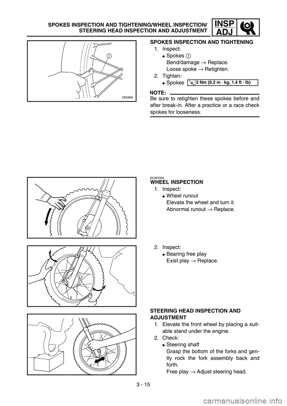
SPOKES INSPECTION AND TIGHTENING
1. Inspect:
�Spokes 1
Bend/damage → Replace.
Loose spoke → Retighten.
2. Tighten:
�Spokes
NOTE:
Be sure to retighten these spokes before and
after break-in. After a practice or a race check
spokes for looseness.
T R..2 Nm (0.2 m · kg, 1.4 ft · lb)
EC36T000
WHEEL INSPECTION
1. Inspect:
�Wheel runout
Elevate the wheel and turn it.
Abnormal runout → Replace.
2. Inspect:
�Bearing free play
Exist play → Replace.
STEERING HEAD INSPECTION AND
ADJUSTMENT
1. Elevate the front wheel by placing a suit-
able stand under the engine.
2. Check:
�Steering shaft
Grasp the bottom of the forks and gen-
tly rock the fork assembly back and
forth.
Free play → Adjust steering head.
Page 166 of 364
3 - 20
INSP
ADJ
ELECTRICAL/SPARK PLUG INSPECTION
EC370000
ELECTRICAL
EC371001
SPARK PLUG INSPECTION
1. Remove:
�Spark plug
2. Inspect:
�Electrode 1
Wear/damage → Replace.
�Insulator color 2
Normal condition is a medium to light
tan color.
Distinctly different color → Check the
engine condition.
NOTE:
When the engine runs for many hours at low
speeds, the spark plug insulator will become
sooty, even if the engine and carburetor are in
good operating condition.
3. Measure:
�Plug gap a
Use a wire gauge or thickness gauge.
Out of specification → Regap.
4. Clean the plug with a spark plug cleaner
if necessary.
Spark plug gap:
0.6 ~ 0.7 mm (0.02 ~ 0.03 in)
Standard spark plug:
CR6HSA (NGK)
U20FSR-U (DENSO)
5. Tighten:
�Spark plug
NOTE:
�Before installing a spark plug, clean the gas-
ket surface and plug surface.
�Finger-tighten a the spark plug before
torquing to specification b.
T R..13 Nm (1.3 m · kg, 9.4 ft · lb)
Page 186 of 364
4 - 1
ENG
ENGINE
CARBURETOR
Extent of removal:
1
Carburetor removal
Extent of removal Order Part name Q’ty Remarks
CARBURETOR REMOVAL
Preparation for removal Fuel tank
1 Clamp (air filter joint) 1 Loosen the screw (air filter joint).
2 Carburetor heater lead 1
3 Air vent hose 1
4 Fuel hose 1
5 Bolt 2
6 Carburetor assembly 1
7 O-ring 1
8 Spacer 1
9 Carburetor top 1
10 Starter plunger assembly 1
1
CARBURETOR
Page 206 of 364

4 - 11
ENGCYLINDER HEAD
4. Remove:
�Cylinder head
NOTE:
�Loosen the bolts and nuts in their proper
loosening sequence.
�Start by loosening each bolt and nut 1/2 turn
until all are loose.
ASSEMBLY AND INSTALLATION
1. Install:
�Cylinder head
2. Tighten:
�Nuts
�Bolts
NOTE:
�Apply the engine oil on the contact surfaces
of the nuts, bolts and copper washers.
�Follow the numerical order shown in the illus-
tration. Tighten the bolts and nuts in two
stages.
T R..22 Nm (2.2 m · kg, 16 ft · lb)
T R..10 Nm (1.0 m · kg, 7.2 ft · lb)
3. Install:
�Camshaft sprocket 1
Installation steps:
�Turn the crankshaft counterclockwise until
the “I” mark a on the rotor is aligned with
the stationary pointer b on the crankcase
cover.
�Align the “I” mark c on the camshaft
sprocket with the stationary pointer d on
the cylinder head.
�Fit the timing chain 2 onto camshaft
sprocket and install the camshaft sprocket
on the camshaft.
NOTE:
When installing the camshaft sprocket, keep
the timing chain as tense as possible on the
exhaust side.
Page 212 of 364
4 - 14
ENGCAMSHAFT AND ROCKER ARMS
REMOVAL POINTS
Rocker arm shaft
1. Remove:
�Rocker arm shafts
NOTE:
Use a slide hammer bolt 1 and weight 2 to
slide out the rocker arm shafts.
Slide hammer set:
YU-1083-A
Slide hammer bolt:
90890-01085
Weight:
90890-01084
INSPECTION
Camshaft
1. Measure:
�Cam lobes length a and b
Out of specification → Replace.
Cam lobes length limit:
Intake:
a 25.398 mm (0.9999 in)
b 21.004 mm (0.8269 in)
Exhaust:
a 25.256 mm (0.9943 in)
b 21.017 mm (0.8274 in)
ASSEMBLY AND INSTALLATION
1. Apply:
�Molybdenum disulfide oil
(onto the camshaft cam lobe)
�Engine oil
(onto the camshaft bearing)
2. Install:
�Camshaft 1