Page 234 of 364
4 - 25
ENGCYLINDER AND PISTON
Piston pin
1. Inspect:
�Piston pin
Blue discoloration/grooves →
Replace, then inspect the lubrication
system.
2. Measure:
�Piston pin outside diameter
�Piston pin bore inside diameter
ASSEMBLY AND INSTALLATION
Piston
1. Install:
�Piston rings
(onto the piston)
NOTE:
�Be sure to install the piston rings so that the
manufacturer’s marks or numbers are
located on the upper side of the rings.
�Lubricate the piston and piston rings liberally
with engine oil. Measurement steps:
�Measure the piston pin outside diameter
a.
If out of specification, replace the piston
pin.
Outside diameter (piston pin):
12.996 ~ 13.000 mm
(0.5117 ~ 0.5118 in)
:12.976 mm (0.5109 in)
�Measure the piston inside diameter b.
If out of specification, replace the piston.
Inside diameter (piston):
13.002 ~ 13.013 mm
(0.5119 ~ 0.5123 in)
: 13.045 mm (0.5136 in)
Page 236 of 364
4 - 26
ENG
CYLINDER AND PISTON
2. Position:
�
Top ring
�
2nd ring
�
Oil ring
Offset the piston ring end gaps as
shown.
a
Top ring end
b
Oil ring end (lower)
c
Oil ring end (upper)
d
2nd ring end
3. Install:
�
Piston
1
�
Piston pin
2
�
Piston pin clips
3
NOTE:
�
Apply engine oil onto the piston pin, piston
ring and piston.
�
Be sure that the arrow mark
a
on the piston
points to the exhaust side of the engine.
�
Before installing the piston pin clip, cover the
crankcase with a clean rag to prevent the
piston pin clip from falling into the crankcase.
4. Lubricate:
�
Piston
�
Piston rings
�
Cylinder
NOTE:
Apply a liberal coating of engine oil.
New
Cylinder
1. Install:
�
Dowel pins
�
Gasket
�
Cylinder
1
NOTE:
Install the cylinder with one hand while com-
pressing the piston rings with the other hand.
CAUTION:
�
Be careful not to damage the timing chain
damper during installation.
�
Pass the timing chain through the timing
chain cavity.
New
Page 238 of 364
4 - 27
ENG
CLUTCH
CLUTCH
CRANKCASE COVER (LEFT AND RIGHT)
Extent of removal:
1
Crankcase cover (left) removal
2
Crankcase cover (right) removal
Extent of removal Order Part name Q’ty Remarks
CRANKCASE COVER (LEFT
AND RIGHT) REMOVAL
Preparation for removal Drain the engine oil. Refer to “ENGINE OIL REPLACEMENT”
section in the CHAPTER 3.
1 Shift pedal 1
2 Drive sprocket cover 1
3 Crankcase cover (left) 1
4 Gasket 1
5 Dowel pin 2
6 Clutch adjusting screw 1
7 Kick crank 1
8 Crankcase cover (right) 1
9 Gasket 1
10 Dowel pin 2
1
2
Page 272 of 364
4 - 44
ENGCDI MAGNETO AND STARTER CLUTCH (TT-R90E)
3. Install:
�Spring 1
�Spring cap 2
�Pin 3
4. Install:
�Shim 1
�Starter wheel gear 2
�Starter idle gear 3
�Shaft 4
NOTE:
�Apply the molybdenum disulfide oil on the
starter wheel gear inner circumference.
�Apply the engine oil on the starter idle gear
inner circumference and on the shaft outer
circumference.
12
3
123
5. Install:
�Woodruff key 1
�Rotor 2
NOTE:
�Clean the tapered portion of the crankshaft
and the magneto hub.
�When installing the magneto rotor, make
sure the woodruff key is properly seated in
the key way of the crankshaft.
6. Tighten:
�Nut (magneto) 1
NOTE:
Tighten the nut (magneto) 1 while holding the
magneto 2 with a sheave holder 3.
7. Install:
�Crankcase cover (left)
NOTE:
�Pass the starter motor lead 1 and neutral
switch lead 2 into the crankcase cover
groove as shown.
�Fasten the starter motor lead with the clamp 3.
Sheave holder:
YS-1880-A/90890-01701
T R..48 Nm (4.8 m · kg, 35 ft · lb)
2
1
1
3
Page 274 of 364
4 - 45
ENGCRANKCASE AND CRANKSHAFT
CRANKCASE AND CRANKSHAFT
Extent of removal Order Part name Q’ty Remarks
CRANKCASE SEPARATION
AND CRANKSHAFT REMOVAL
Preparation for removal Seat, fuel tank and rear fender
Exhaust pipe
Air filter case
Carburetor Refer to “CARBURETOR” section.
Drain the engine oil Refer to “ENGINE OIL REPLACEMENT”
section in the CHAPTER 3.
Engine guard and drive sprocket
Engine assembly From the chassis.
Cylinder head Refer to “CYLINDER HEAD” section.
Cylinder and piston Refer to “CYLINDER AND PISTON” sec-
tion.
Clutch housing and clutch carrier Refer to “CLUTCH” section.
Kick axle assembly Refer to “KICK AXLE” section.
Page 280 of 364
4 - 48
ENGSHIFT FORK, SHIFT CAM AND TRANSMISSION
SHIFT FORK, SHIFT CAM AND TRANSMISSION
Extent of removal:1 Shift fork, shift cam, main axle and drive axle removal
2 Main axle disassembly3 Drive axle disassembly
Extent of removal Order Part name Q’ty Remarks
SHIFT FORK, SHIFT CAM
TRANSMISSION REMOVAL
Preparation for removal Engine assembly
Separate the crankcase. Refer to “CRANKCASE AND CRANK-
SHAFT” section.
1 Guide bar 1
2 Shift cam 1
Refer to “REMOVAL POINTS”. 3 Shift fork 2 “R”1
4 Shift fork 1 “L”1
5 Drive axle assembly 1
6 Main axle assembly 1
7 2nd pinion gear 1
8 Circlip 1
9 Washer 1
1
2
Page 284 of 364
4 - 50
ENGSHIFT FORK, SHIFT CAM AND TRANSMISSION
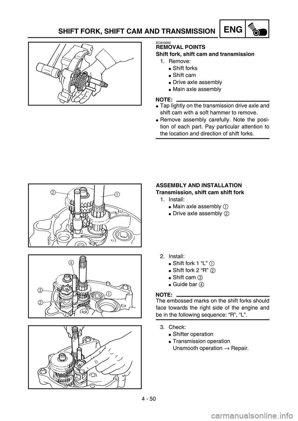
EC4H3000
REMOVAL POINTS
Shift fork, shift cam and transmission
1. Remove:
�Shift forks
�Shift cam
�Drive axle assembly
�Main axle assembly
NOTE:
�Tap lightly on the transmission drive axle and
shift cam with a soft hammer to remove.
�Remove assembly carefully. Note the posi-
tion of each part. Pay particular attention to
the location and direction of shift forks.
ASSEMBLY AND INSTALLATION
Transmission, shift cam shift fork
1. Install:
�Main axle assembly 1
�Drive axle assembly 2
2. Install:
�Shift fork 1 “L” 1
�Shift fork 2 “R” 2
�Shift cam 3
�Guide bar 4
NOTE:
The embossed marks on the shift forks should
face towards the right side of the engine and
be in the following sequence: “R”, “L”.
3. Check:
�Shifter operation
�Transmission operation
Unsmooth operation → Repair.
Page 286 of 364
5 - 1
CHAS
EC500000
CHASSIS
FRONT WHEEL AND REAR WHEEL
FRONT WHEEL AND FRONT BRAKE
FRONT WHEEL AND REAR WHEEL
Extent of removal:
1
Front wheel removal
2
Wheel bearing removal
3
Brake shoe plate assembly removal and disassembly
Extent of removal Order Part name Q’ty Remarks
FRONT WHEEL REMOVAL
WARNING
Support the machine securely so there is no
danger of it falling over.
Preparation for removal Hold the machine by placing the
suitable stand under the engine.
1 Bolt (brake cable holder) 1 Only loosening.
2 Brake cable 1 Disconnect at the lever side.
3 Wheel axle nut 1
4 Front wheel axle 1
5 Front wheel 1
6 Collar set 1
7 Brake shoe plate assembly 1
8 Oil seal 1
9Bearing
2Refer to “REMOVAL POINTS”.
2
31
3


Extent of removal:
1
Crankcase cover (left) removal
2
Crankcase cover (right) removal
Extent of removal Order Part name Q’ty Re")