Page 120 of 364

2 - 23
SPECCABLE ROUTING DIAGRAM
ÅPass the start switch lead, main
switch lead, engine stop switch
lead and throttle cable through
the cable guide.
ıPass the fuel tank breather hose
through the hose guide.
ÇPass the carburetor breather
hose through the hose guide.
ÎFasten the carburetor heater lead,
main switch lead, engine stop
switch lead and start switch lead.‰After fastening the CDI mag-
neto lead, cut off any excess
from the plastic locking tie end.
ÏFasten the battery leads to the
bracket with the plastic locking
tie. For fastening, pass the plas-
tic locking tie through the hole in
the bracket.
ÌAfter fastening the starter motor
lead, cut off any excess from the
plastic locking tie end.ÓAfter fastening the CDI mag-
neto lead, cut off any excess
from the plastic locking tie end.
ÈPosition the start switch coupler
and engine stop switch coupler
between the carburetor breather
hose and thermo switch.
ÔMake sure that the CDI unit lead
does not contact the thermo
switch bracket.
A AA
C C
D
B
B B
BF FF
EE
D
A - AB - BE - E
C
F - FG - GD
KK
QRÔ
8
E
H
˜ 2 3 4
6
5
4
3
2
1
J
I
H
G
F
E
D
CBA 0 Ï 9 8 Î K 7
S
W U
V
A
0
Í T
99
QP
PT
9
Ò
ˆ Ø
Ç ı
Å
Ó
Œ
Â
E
GGA
P
O
NML 9
È
9
Ì
Ê
◊
25 mm (1.0 in)
∏
‰
35 ~ 45 mm
(1.38 ~ 1.77 in)
30 ~ 40 mm
(1.18 ~ 1.57 in)
Ë
Page 122 of 364

2 - 24
SPEC
Fasten the starter cable, thermo
switch lead, CDI unit lead, main
switch lead, start switch lead
and engine stop switch lead.
ÒFasten the wire harness, CDI
unit leads, thermo switch lead
and CDI magneto lead.
˜Pass the carburetor heater lead
between the carburetor breather
hose and air intake duct.ˆPosition the main switch cou-
pler between the carburetor
breather hose and air intake
duct.
ØFasten the start switch lead,
main switch lead and engine
stop switch lead at the tape with
the plastic locking tie.
∏Fasten the battery leads.ŒFasten the wire harness and
starting circuit cut-off relay lead
at the tape for the wire harness
with the plastic locking tie.
ÂFasten the rectifier/regulator
lead and starter relay leads. For
fastening, pass the plastic lock-
ing tie through the hole in the
battery box.
A AA
C C
D
B
B B
BF FF
EE
D
A - AB - BE - E
C
F - FG - GD
KK
QRÔ
8
E
H
˜ 2 3 4
6
5
4
3
2
1
J
I
H
G
F
E
D
CBA 0 Ï 9 8 Î K 7
S
W U
V
A
0
Í T
99
QP
PT
9
Ò
ˆ Ø
Ç ı
Å
Ó
Œ
Â
E
GGA
P
O
NML 9
È
9
Ì
Ê
◊
25 mm (1.0 in)
∏
‰
35 ~ 45 mm
(1.38 ~ 1.77 in)
30 ~ 40 mm
(1.18 ~ 1.57 in)
Ë
CABLE ROUTING DIAGRAM
Page 132 of 364

3 - 3
INSP
ADJ
ENGINE/THROTTLE CABLE ADJUSTMENT/
AIR FILTER CLEANING
EC350000
ENGINE
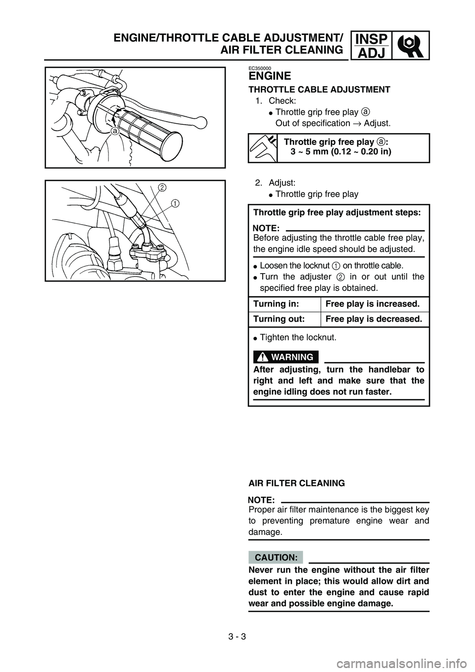
THROTTLE CABLE ADJUSTMENT
1. Check:
�
Throttle grip free play
a
Out of specification
→
Adjust.
Throttle grip free play
a
:
3 ~ 5 mm (0.12 ~ 0.20 in)
2. Adjust:
�
Throttle grip free play
AIR FILTER CLEANING
NOTE:
Proper air filter maintenance is the biggest key
to preventing premature engine wear and
damage.
CAUTION:
Never run the engine without the air filter
element in place; this would allow dirt and
dust to enter the engine and cause rapid
wear and possible engine damage.Throttle grip free play adjustment steps:
NOTE:
Before adjusting the throttle cable free play,
the engine idle speed should be adjusted.
�
Loosen the locknut
1
on throttle cable.
�
Turn the adjuster
2
in or out until the
specified free play is obtained.
Turning in: Free play is increased.
Turning out: Free play is decreased.
�
Tighten the locknut.
WARNING
After adjusting, turn the handlebar to
right and left and make sure that the
engine idling does not run faster.
Page 144 of 364

3 - 9
INSP
ADJ
VALVE CLEARANCE ADJUSTMENT
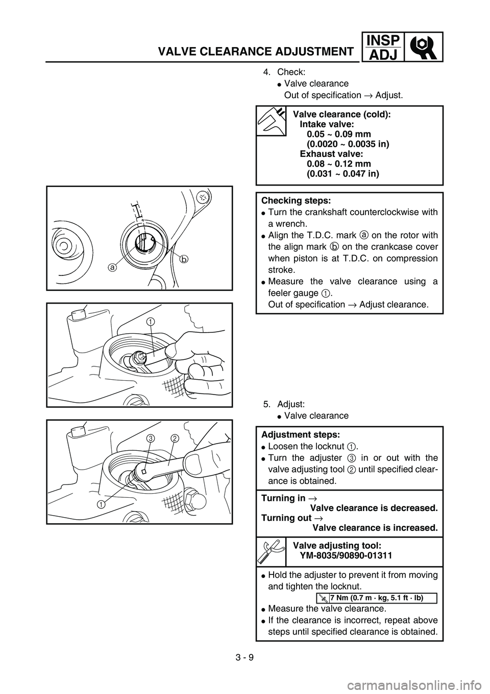
4. Check:
�Valve clearance
Out of specification → Adjust.
5. Adjust:
�Valve clearance
Valve clearance (cold):
Intake valve:
0.05 ~ 0.09 mm
(0.0020 ~ 0.0035 in)
Exhaust valve:
0.08 ~ 0.12 mm
(0.031 ~ 0.047 in)
Checking steps:
�Turn the crankshaft counterclockwise with
a wrench.
�Align the T.D.C. mark a on the rotor with
the align mark b on the crankcase cover
when piston is at T.D.C. on compression
stroke.
�Measure the valve clearance using a
feeler gauge 1.
Out of specification → Adjust clearance.
Adjustment steps:
�Loosen the locknut 1.
�Turn the adjuster 3 in or out with the
valve adjusting tool 2 until specified clear-
ance is obtained.
Turning in →
Valve clearance is decreased.
Turning out →
Valve clearance is increased.
Valve adjusting tool:
YM-8035/90890-01311
�Hold the adjuster to prevent it from moving
and tighten the locknut.
�Measure the valve clearance.
�If the clearance is incorrect, repeat above
steps until specified clearance is obtained.
1
12 3
T R..7 Nm (0.7 m · kg, 5.1 ft · lb)
Page 148 of 364
3 - 11
INSP
ADJCHASSIS/FRONT BRAKE ADJUSTMENT/
REAR BRAKE ADJUSTMENT
CHASSIS
FRONT BRAKE ADJUSTMENT
1. Check:
�Brake lever free play a
Out of specification → Adjust.
Free play (brake lever):
10 ~ 20 mm (0.39 ~ 0.79 in)
(at brake lever end)
a
21
2. Adjust:
�Brake lever free play
REAR BRAKE ADJUSTMENT
1. Check:
�Brake pedal free play a
Out of specification → Adjust.
2. Adjust:
�Brake pedal free play Adjustment steps:
�Loosen the locknuts 1.
�Turn the adjusters 2 in or out until the
specified free play is obtained.
Turning in: Free play is increased.
Turning out: Free play is decreased.
�Tighten the locknuts.
CAUTION:
Make sure that there is no brake drag
after adjusting the front brake lever free
play.
Free play:
10 ~ 20 mm (0.39 ~ 0.79 in)
Adjustment steps:
�Turn the adjuster 1 in or out until the
specified free play is obtained.
Turning in: Free play is decreased.
Turning out: Free play is increased.
CAUTION:
Make sure that the brake does not drag
after adjusting it.
1
a
Page 150 of 364

3 - 12
INSP
ADJ
DRIVE CHAIN SLACK ADJUSTMENT
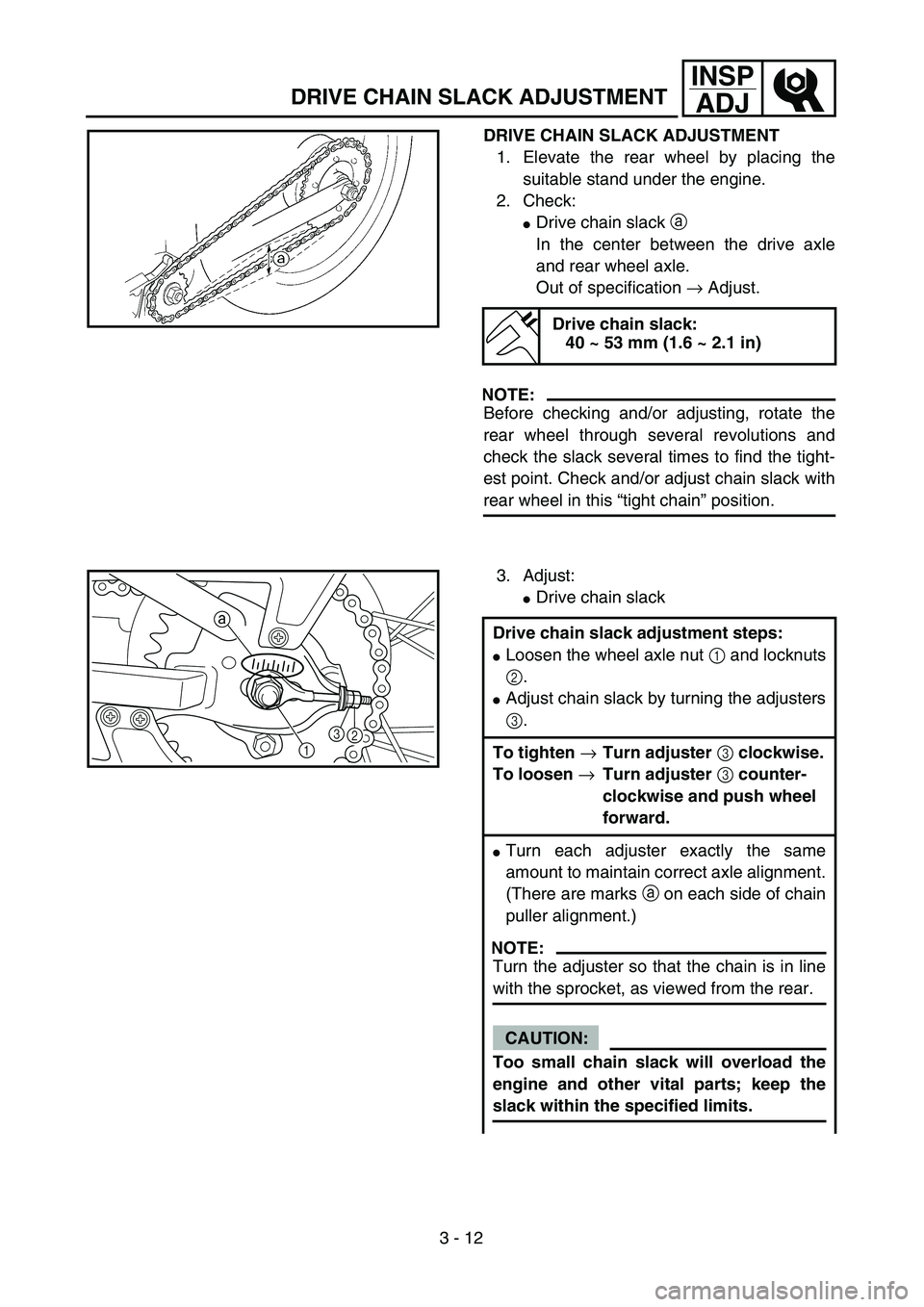
DRIVE CHAIN SLACK ADJUSTMENT
1. Elevate the rear wheel by placing the
suitable stand under the engine.
2. Check:
�Drive chain slack a
In the center between the drive axle
and rear wheel axle.
Out of specification → Adjust.
NOTE:
Before checking and/or adjusting, rotate the
rear wheel through several revolutions and
check the slack several times to find the tight-
est point. Check and/or adjust chain slack with
rear wheel in this “tight chain” position.
Drive chain slack:
40 ~ 53 mm (1.6 ~ 2.1 in)
3. Adjust:
�Drive chain slack
Drive chain slack adjustment steps:
�Loosen the wheel axle nut 1 and locknuts
2.
�Adjust chain slack by turning the adjusters
3.
To tighten →Turn adjuster 3 clockwise.
To loosen →Turn adjuster 3 counter-
clockwise and push wheel
forward.
�Turn each adjuster exactly the same
amount to maintain correct axle alignment.
(There are marks a on each side of chain
puller alignment.)
NOTE:
Turn the adjuster so that the chain is in line
with the sprocket, as viewed from the rear.
CAUTION:
Too small chain slack will overload the
engine and other vital parts; keep the
slack within the specified limits.
13 a2
Page 151 of 364

INSP
ADJ
ANTRIEBSKETTEN-DURCHHANG
EINSTELLEN
1. Das Motorrad am Motor aufbocken, um
das Hinterrad vom Boden abzuheben.
2. Kontrollieren:
�Antriebsketten-Durchhang a
über der Kettenführungs-Schraube.
Unvorschriftsmäßig → Einstellen.
HINWEIS:
Vor dem Prüfen oder dem Einstellen des Ket-
tendurchhangs das Hinterrad mehrere Umdre-
hungen durchdrehen und den
Kettendurchhang über die gesamte Länge der
Kette prüfen. Die Einstellung des Kettenspiels
muß an der straffsten Stelle der Kette vorge-
nommen werden.
Antriebsketten-Durchhang:
40–53 mm (1,6–2,1 in)
3. Einstellen:
�Antriebsketten-Durchhang
Arbeitsschritte:
�Achsmutter 1 und Gegenmuttern 2
lösen.
�Einstellschrauben 3 verdrehen, bis der
vorgeschriebene Kettendurchhang
erreicht ist.
Zum Straffen der Kette die Einstellmutter
3 im Uhrzeigersinn drehen.
Zum Lockern der Kette die Einstellmutter
3 im Gegenuhrzeigersinn drehen und
Rad nach vorn drücken.
�Beide Kettenspanner jeweils gleichmäßig
einstellen, damit die Ausrichtung sich nicht
verstellt. (Die Markierungen a auf beiden
Kettenspannern dienen zum korrekten
Ausrichten des Hinterrads.)
HINWEIS:
Die Kette muß von hinten blickend mit dem
Kettenrad fluchten.
ACHTUNG:
Eine zu straff gespannte Kette verursacht
erhöhten Verschleiß von Motor, Lagern
und anderen wichtigen Bauteilen. Daher
darauf achten, daß der Kettendurchhang
sich im Sollbereich befindet.
REGLAGE DE LA TENSION DE LA CHAINE DE TRANSMISSION
ANTRIEBSKETTEN-DURCHHANG EINSTELLEN
REGLAGE DE LA TENSION DE LA CHAINE
DE TRANSMISSION
1. Surélever la roue arrière en plaçant un sup-
port adéquat sous le moteur.
2. Contrôler:
�Flèche de la chaîne de transmission a
Au point central entre l’arbre secondaire et
l’axe de roue arrière.
Hors spécifications → Régler.
N.B.:
Avant d’entamer le contrôle et/ou le réglage, faire
tourner la roue arrière plusieurs fois afin de trouver
la position de la roue où la chaîne semble la plus
tendue. C’est dans cette position qu’il faut contrô-
ler et régler la tension de la chaîne.
Flèche de la chaîne de transmission:
40 à 53 mm (1,6 à 2,1 in)
3. Régler:
�Flèche de la chaîne de transmission
Etapes du réglage de la flèche de la chaîne de
transmission:
�Desserrer l’écrou d’axe de roue 1 et les con-
tre-écrous 2.
�Régler le flèche de la chaîne en tournant les
dispositifs de réglage 3.
Pour serrer →Tourner le dispositif de
réglage 3 dans le sens des
aiguilles d’une montre.
Pour desserrer →Tourner le dispositif de
réglage 3 dans le sens
inverse des aiguilles d’une
montre, puis repousser la
roue vers l’avant.
�Tourner chaque dispositif de réglage de la
même façon afin de garantir un alignement
d’axe correct. (Des repères d’alignement a
figurent de chaque côté du tendeur de chaîne.)
N.B.:
Tourner le tendeur de sorte que la chaîne s’ali-
gne sur la couronne, vu de l’arrière.
ATTENTION:
Une flèche trop petite impose un effort exces-
sifs au moteur et à d’autres organes vitaux.
Maintenir la flèche dans les limites spécifiées.
3 - 12
Page 152 of 364
3 - 13
INSP
ADJFRONT FORK INSPECTION/REAR SHOCK ABSORBER INSPECTION/
REAR SHOCK ABSORBER SPRING PRELOAD ADJUSTMENT
�Tighten the wheel axle nut while pushing
down the drive chain.
T R..
Axle nut:
60 Nm (6.0 m • kg, 43 ft • lb)
�Tighten the locknuts.
T R..
Locknut:
7 Nm (0.7 m • kg, 5.1 ft • lb)
EC36C000
FRONT FORK INSPECTION
1. Inspect:
�Front fork smooth action
Operate the front brake and stroke the
front fork.
Unsmooth action/oil leakage → Repair
or replace.
EC36K000
REAR SHOCK ABSORBER INSPECTION
1. Inspect:
�Swingarm smooth action
Abnormal noise/unsmooth action →
Grease the pivoting points or repair the
pivoting points.
Damage/oil leakage → Replace.
REAR SHOCK ABSORBER SPRING
PRELOAD ADJUSTMENT
1. Elevate the rear wheel by placing the
suitable stand under the engine.
2. Remove:
�Rear shock absorber
Refer to “SWINGARM” section in the
CHAPTER 5.
3. Remove:
�Spring guide 1
NOTE:
While compressing the spring, remove the
spring guide.