Page 49 of 92

PERIODIC MAINTENANCE AND MINOR REPAIR
6-8
2
3
4
5
67
8
9
and then remove it again to check
the oil level.
NOTE:
The engine oil should be between the
minimum and maximum level marks.
CAUTION:
ECA10010
Do not operate the vehicle until you
know that the engine oil level is suf-
ficient.
WARNING
EWA10360
Never remove the engine oil tank
cap after high-speed operation, oth-
erwise hot engine oil could spout
out and cause damage or injury. Al-
ways let the engine oil cool down
sufficiently before removing the oil
tank cap.
4. If the engine oil is below the mini-
mum level mark, add sufficient oil
of the recommended type to raise
it to the correct level.
5. Install the oil filler cap.
NOTE:
�
The engine oil tank is located be-
hind the cylinders.
�
The engine oil should be between
the minimum and maximum level
marks.
To change the engine oil (with or
without oil filter element replace-
ment)
1. Start the engine, warm it up for
several minutes, and then turn it
off.
2. Place an oil pan under the engine
to collect the used oil.
3. Remove the engine oil filler cap
and drain bolts to drain the oil from
the crankcase.
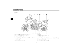
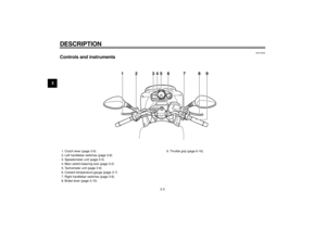
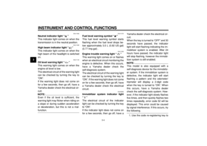
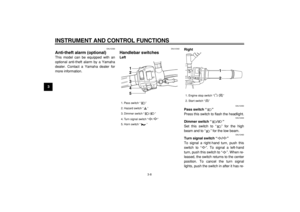
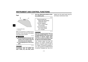
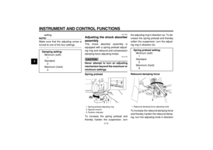
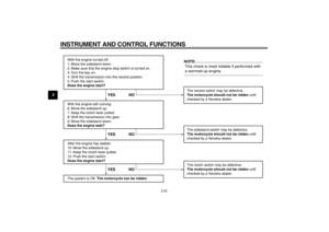
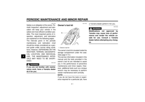
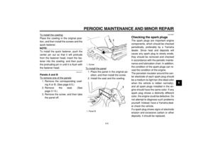
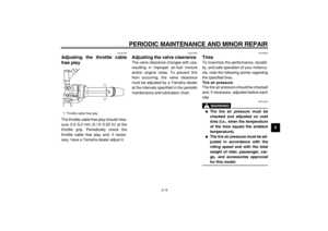
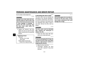
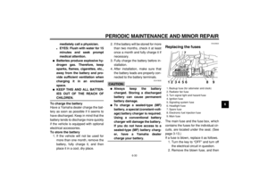
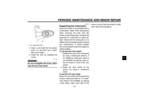
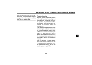
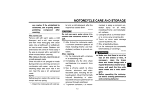
1. Engine oil filler cap
1
1. Engine oil filler cap
2. Dipstick
3. Maximum level mark
4. Minimum level mark
1
2
3
4
Page 50 of 92
PERIODIC MAINTENANCE AND MINOR REPAIR
6-9
1
2
3
4
5
6
7
8
9
NOTE:
Skip steps 4–6 if the oil filter element is
not being replaced.
4. Remove the oil filter element cover
by removing the bolts.5. Remove and replace the oil filter
element and O-rings.
6. Install the oil filter element cover byinstalling the bolts, then tightening
them to the specified torque.
NOTE:
Make sure that the O-rings are properly
seated.
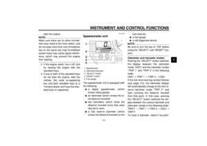
7. Install the engine oil drain bolts,
and then tighten them to the spec-
ified torques.
8. Add the specified amount of the
recommended engine oil, and then
install and tighten the oil filler cap.
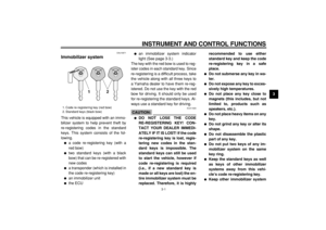
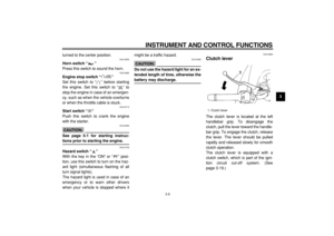
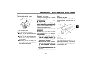
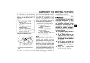
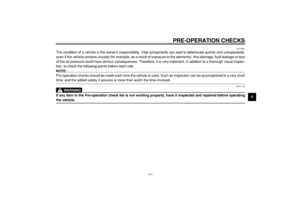
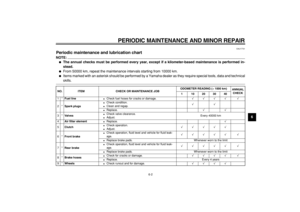
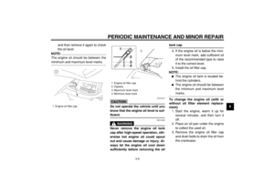
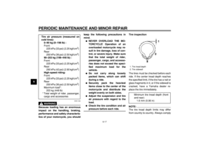
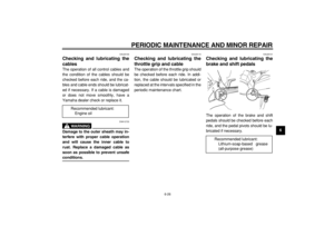
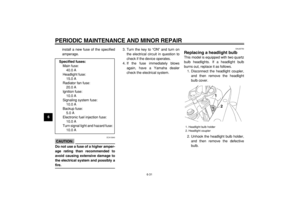
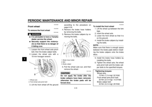
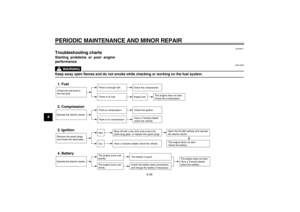
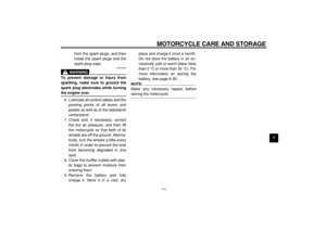
1. Engine oil drain bolt A
1
1. Engine oil drain bolt B
2. Oil filter element cover
3. Bolt
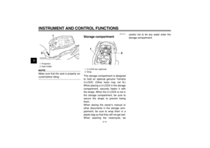
1. Oil filter element
2. O-ring
12
2
3
1
2
Tightening torque:
Oil filter element cover bolt:
10 Nm (1.0 m·kgf, 7.2 ft·lbf)
Tightening torques:
Engine oil drain bolt A:
35 Nm (3.5 m·kgf, 25 ft·lbf)
Engine oil drain bolt B:
35 Nm (3.5 m·kgf, 25 ft·lbf)
Page 51 of 92
, do not
mix any chemical")
PERIODIC MAINTENANCE AND MINOR REPAIR
6-10
2
3
4
5
67
8
9
CAUTION:
ECA11620
�
In order to prevent clutch slip-
page (since the engine oil also
lubricates the clutch), do not
mix any chemical additives. Do
not use oils with a diesel speci-
fication of “CD” or oils of a high-
er quality than specified. In
addition, do not use oils labeled
“ENERGY CONSERVING II” or
higher.
�
Make sure that no foreign mate-
rial enters the crankcase.
9. Start the engine, and then let it idlefor several minutes while checking
it for oil leakage. If oil is leaking, im-
mediately turn the engine off and
check for the cause.
10. Turn the engine off, and then
check the oil level and correct it if
necessary.
EAU20070
Coolant
The coolant level should be checked
before each ride. In addition, the cool-
ant must be changed at the intervals
specified in the periodic maintenance
and lubrication chart.
EAU20101
To check the coolant level
1. Place the vehicle on the center-
stand.
NOTE:
�
The coolant level must be checked
on a cold engine since the level
varies with engine temperature.
�
Make sure that the vehicle is posi-
tioned straight up when checking
the coolant level. A slight tilt to the
side can result in a false reading.
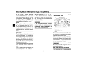
2. Check the coolant level in the cool-
ant reservoir.
NOTE:
The coolant should be between the
minimum and maximum level marks. Recommended engine oil:
See page 8-1.
Oil quantity:
Without oil filter element replace-
ment:
3.80 L (4.02 US qt)
(3.34 Imp.qt)
With oil filter element replace-
ment:
3.90 L (4.12 US qt)
(3.43 Imp.qt)
Page 52 of 92
, remove the
reservoir cap, add coolant to th")
PERIODIC MAINTENANCE AND MINOR REPAIR
6-11
1
2
3
4
5
6
7
8
9
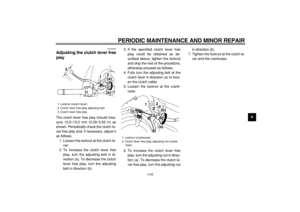
3. If the coolant is at or below the
minimum level mark, remove pan-
el B (See page 6-5.), remove the
reservoir cap, add coolant to the
maximum level mark, and then in-
stall the reservoir cap and the pan-
el.
CAUTION:
ECA10470
�
If coolant is not available, use
distilled water or soft tap water
instead. Do not use hard water
or salt water since it is harmful
to the engine.
�
If water has been used instead
of coolant, replace it with cool-
ant as soon as possible, other-
wise the engine may not be
sufficiently cooled and the cool-ing system will not be protected
against frost and corrosion.
�
If water has been added to the
coolant, have a Yamaha dealer
check the antifreeze content of
the coolant as soon as possible,
otherwise the effectiveness of
the coolant will be reduced.
WARNING
EWA10380
Never attempt to remove the radiator
cap when the engine is hot.
NOTE:
�
The radiator fan is automatically
switched on or off according to the
coolant temperature in the radia-
tor.
�
If the engine overheats, see page
6-39 for further instructions.
EAU20450
To change the coolant
1. Place the vehicle on a level sur-
face and let the engine cool if nec-
essary.
2. Remove the seat. (See
page 3-13.)
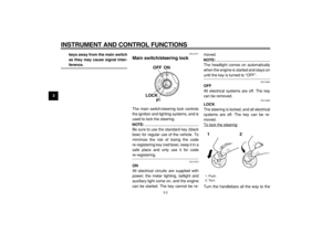
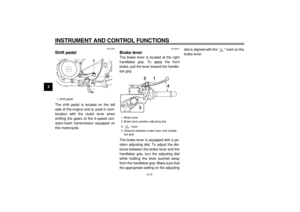
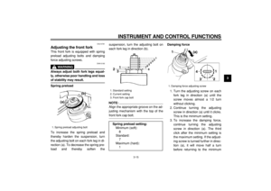
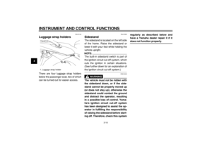
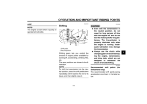
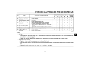
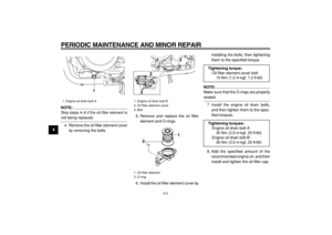
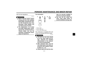
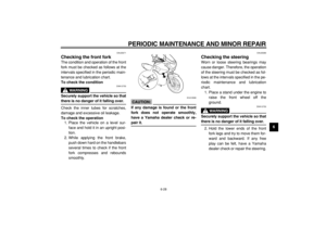
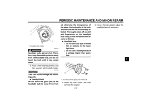
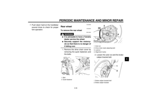
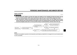
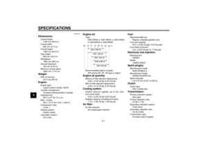
1. Coolant reservoir
2. Maximum level mark
3. Minimum level mark
1 2
3
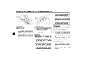
1. Coolant reservoir cap
Coolant reservoir capacity (up to
the maximum level mark):
0.25 L (0.26 US qt)
(0.22 Imp.qt)
1
Page 53 of 92

4. Remove the fuel tank bolts, and
then lift the fuel tank to position it
away from the")
PERIODIC MAINTENANCE AND MINOR REPAIR
6-12
2
3
4
5
67
8
9
3. Remove cowling B and panel B.
(See page 6-5.)
4. Remove the fuel tank bolts, and
then lift the fuel tank to position it
away from the coolant reservoir.
(Do not disconnect the fuel hoses!)
5. Place a container under the engine
to collect the used coolant.
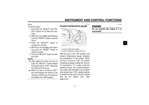
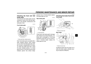
6. Remove the radiator cap retaining
bolt and the radiator cap.
WARNING
EWA10380
Never attempt to remove the radiator
cap when the engine is hot.
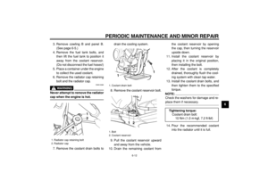
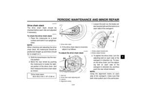
7. Remove the coolant drain bolts todrain the cooling system.
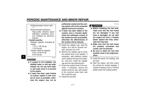
8. Remove the coolant reservoir bolt.
9. Pull the coolant reservoir upward
and away from the vehicle.
10. Drain the remaining coolant fromthe coolant reservoir by opening
the cap, then turning the reservoir
upside down.
11. Install the coolant reservoir by
placing it in the original position,
then installing the bolt.
12. After the coolant is completely
drained, thoroughly flush the cool-
ing system with clean tap water.
13. Install the coolant drain bolts, and
then tighten them to the specified
torque.
NOTE:
Check the washers for damage and re-
place them if necessary.
14. Pour the recommended coolant
into the radiator until it is full.
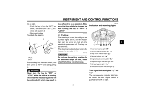
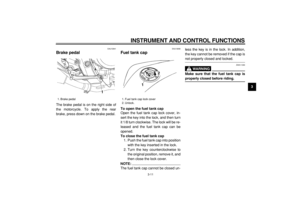
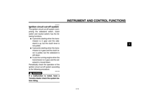
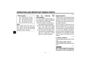
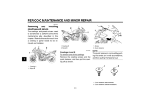
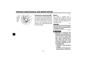
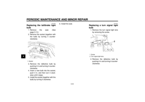
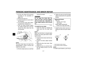
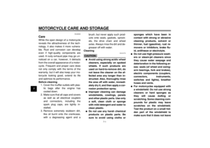
1. Radiator cap retaining bolt
2. Radiator cap
1
2
1. Coolant drain bolt
1. Bolt
2. Coolant reservoir
11
1
2
Tightening torque:
Coolant drain bolt:
10 Nm (1.0 m·kgf, 7.2 ft·lbf)
Page 54 of 92

PERIODIC MAINTENANCE AND MINOR REPAIR
6-13
1
2
3
4
5
6
7
8
9
CAUTION:
ECA10470
�
If coolant is not available, use
distilled water or soft tap water
instead. Do not use hard water
or salt water since it is harmful
to the engine.
�
If water has been used instead
of coolant, replace it with cool-
ant as soon as possible, other-
wise the engine may not besufficiently cooled and the cool-
ing system will not be protected
against frost and corrosion.
�
If water has been added to the
coolant, have a Yamaha dealer
check the antifreeze content of
the coolant as soon as possible,
otherwise the effectiveness of
the coolant will be reduced.
15. Install the radiator cap, start the
engine, let it idle for several min-
utes, and then turn it off.
16. Remove the radiator cap to check
the coolant level in the radiator. If
necessary, add sufficient coolant
until it reaches the top of the radia-
tor, and then install the radiator
cap and the cap retaining bolt.
17. Check the coolant level in the res-
ervoir. If necessary, remove the
coolant reservoir cap, add coolant
to the maximum level mark, and
then install the cap.
18. Install the fuel tank.
WARNING
EWA11290
�
Before installing the fuel tank,
make sure that the fuel hoses
are not damaged. If any fuel
hose is damaged, do not start
the engine but have a Yamaha
dealer replace the hose, other-
wise fuel may leak.
�
Make sure that the fuel hoses
are properly connected and
routed, and not pinched.
�
Be sure to place the fuel tank
breather hose in the original po-
sition.
19. Install the panel, the cowling, and
the seat.
20. Start the engine, and then check
the vehicle for coolant leakage. If
coolant is leaking, have a Yamaha
dealer check the cooling system. Antifreeze/water mixture ratio:
1:1
Recommended antifreeze:
High-quality ethylene glycol
antifreeze containing corro-
sion inhibitors for aluminum
engines
Coolant quantity:
Radiator capacity (including all
routes):
1.70 L (1.80 US qt)
(1.50 Imp.qt)
Coolant reservoir capacity:
0.25 L (0.26 US qt)
(0.22 Imp.qt)
Page 55 of 92

PERIODIC MAINTENANCE AND MINOR REPAIR
6-14
2
3
4
5
67
8
9
EAU27050
Replacing the air filter element
The air filter element should be re-
placed at the intervals specified in the
periodic maintenance and lubrication
chart. Replace the air filter element
more frequently if you are riding in un-
usually wet or dusty areas.
1. Remove the seat. (See
page 3-13.)
2. Remove cowlings A and B as well
as panels A and B. (See
page 6-5.)
3. Remove the fuel tank bolts, and
then lift the fuel tank away from the
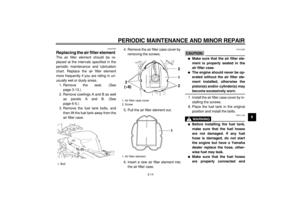
air filter case.4. Remove the air filter case cover by
removing the screws.
5. Pull the air filter element out.
6. Insert a new air filter element into
the air filter case.
CAUTION:
ECA10480
�
Make sure that the air filter ele-
ment is properly seated in the
air filter case.
�
The engine should never be op-
erated without the air filter ele-
ment installed, otherwise the
piston(s) and/or cylinder(s) may
become excessively worn.
7. Install the air filter case cover by in-
stalling the screws.
8. Place the fuel tank in the original
position and install the bolts.
WARNING
EWA11330
�
Before installing the fuel tank,
make sure that the fuel hoses
are not damaged. If any fuel
hose is damaged, do not start
the engine but have a Yamaha
dealer replace the hose, other-
wise fuel may leak.
�
Make sure that the fuel hoses
are properly connected and
1. Bolt
1(×2)
1. Air filter case cover
2. Screw
1. Air filter element
1 2
2 2
(×8)
1
Page 56 of 92

PERIODIC MAINTENANCE AND MINOR REPAIR
6-15
1
2
3
4
5
6
7
8
9routed, and not pinched.
�
Be sure to place the fuel tank
breather hose and the fuel tank
overflow hose in the original po-
sition.
9. Install the panels and cowlings.
10. Install the seat.
EAU21320
Adjusting the engine idling
speed
The engine idling speed must be
checked and, if necessary, adjusted as
follows at the intervals specified in the
periodic maintenance and lubrication
chart.
The engine should be warm before
making this adjustment.
NOTE:
The engine is warm when it quickly re-
sponds to the throttle.
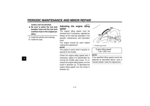
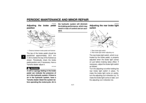
Check the engine idling speed and, if
necessary, adjust it to specification by
turning the throttle stop screw. To in-
crease the engine idling speed, turn the
screw in direction (a). To decrease the
engine idling speed, turn the screw in
direction (b).
NOTE:
If the specified idling speed cannot be
obtained as described above, have a
Yamaha dealer make the adjustment.
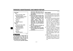
1. Throttle stop screw
Engine idling speed:
1100–1200 r/min
1(a)
(b)