2004 VOLVO S80 ignition
[x] Cancel search: ignitionPage 76 of 110
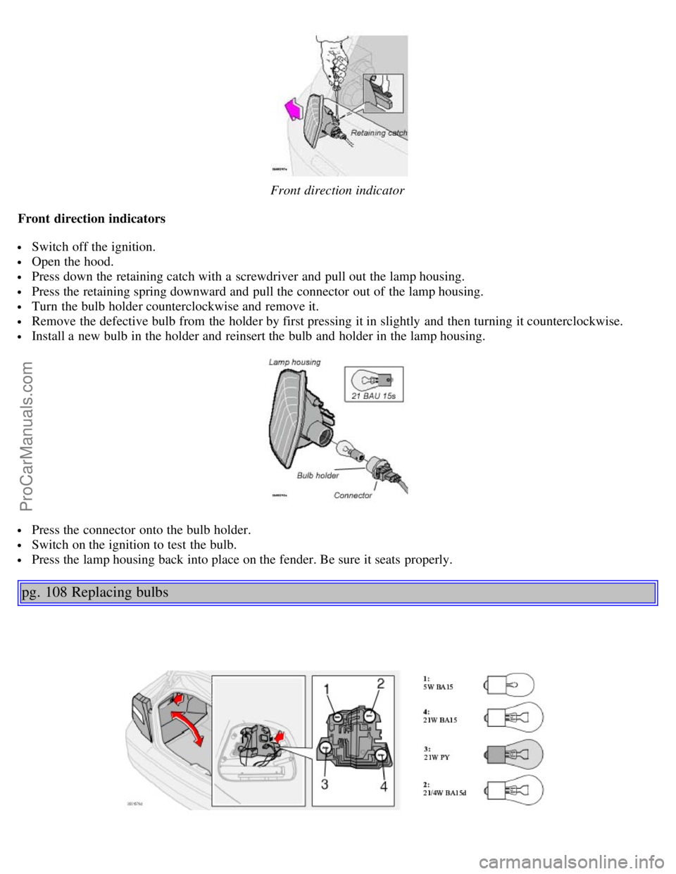
Front direction indicator
Front direction indicators
Switch off the ignition.
Open the hood.
Press down the retaining catch with a screwdriver and pull out the lamp housing.
Press the retaining spring downward and pull the connector out of the lamp housing.
Turn the bulb holder counterclockwise and remove it.
Remove the defective bulb from the holder by first pressing it in slightly and then turning it counterclockwise.
Install a new bulb in the holder and reinsert the bulb and holder in the lamp housing.
Press the connector onto the bulb holder.
Switch on the ignition to test the bulb.
Press the lamp housing back into place on the fender. Be sure it seats properly.
pg. 108 Replacing bulbs
ProCarManuals.com
Page 77 of 110
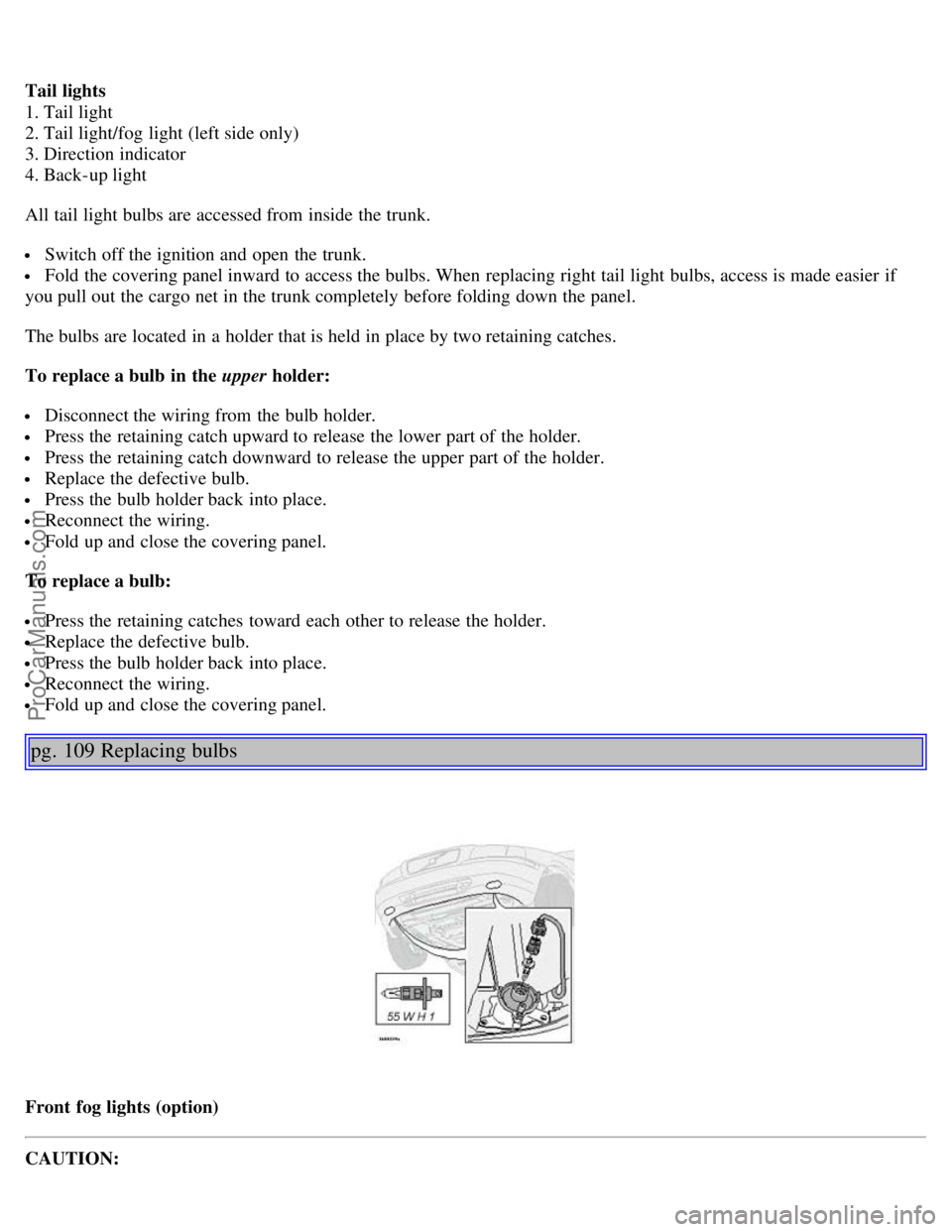
Tail lights
1. Tail light
2. Tail light/fog light (left side only)
3. Direction indicator
4. Back-up light
All tail light bulbs are accessed from inside the trunk.
Switch off the ignition and open the trunk.
Fold the covering panel inward to access the bulbs. When replacing right tail light bulbs, access is made easier if
you pull out the cargo net in the trunk completely before folding down the panel.
The bulbs are located in a holder that is held in place by two retaining catches.
To replace a bulb in the upper holder:
Disconnect the wiring from the bulb holder.
Press the retaining catch upward to release the lower part of the holder.
Press the retaining catch downward to release the upper part of the holder.
Replace the defective bulb.
Press the bulb holder back into place.
Reconnect the wiring.
Fold up and close the covering panel.
To replace a bulb:
Press the retaining catches toward each other to release the holder.
Replace the defective bulb.
Press the bulb holder back into place.
Reconnect the wiring.
Fold up and close the covering panel.
pg. 109 Replacing bulbs
Front fog lights (option)
CAUTION:
ProCarManuals.com
Page 78 of 110
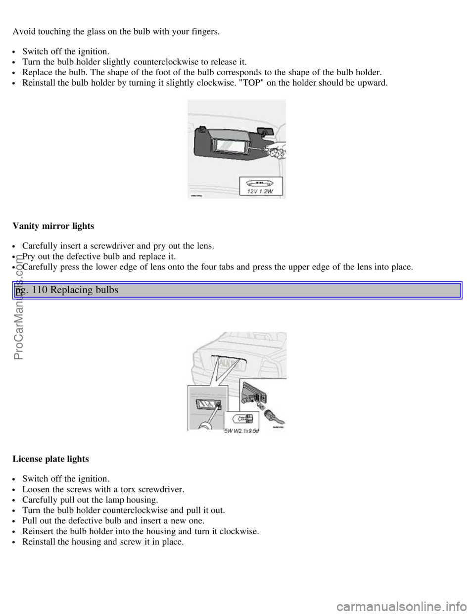
Avoid touching the glass on the bulb with your fingers.
Switch off the ignition.
Turn the bulb holder slightly counterclockwise to release it.
Replace the bulb. The shape of the foot of the bulb corresponds to the shape of the bulb holder.
Reinstall the bulb holder by turning it slightly clockwise. "TOP" on the holder should be upward.
Vanity mirror lights
Carefully insert a screwdriver and pry out the lens.
Pry out the defective bulb and replace it.
Carefully press the lower edge of lens onto the four tabs and press the upper edge of the lens into place.
pg. 110 Replacing bulbs
License plate lights
Switch off the ignition.
Loosen the screws with a torx screwdriver.
Carefully pull out the lamp housing.
Turn the bulb holder counterclockwise and pull it out.
Pull out the defective bulb and insert a new one.
Reinsert the bulb holder into the housing and turn it clockwise.
Reinstall the housing and screw it in place.
ProCarManuals.com
Page 80 of 110
2 0 0 4
VOLVO S80
Chapter 9 - Specifications
pg. 129 Specifications
Label information130
Dimensions and weights131
Engine/transmission specifications132
Oil/fluid specifications and volumes133
Fuel system, distributor ignition system, suspension134
Electrical system135
On Call Roadside Assistance136
pg. 130 Label information
1 Vehicle Emission Control Information
Your Volvo is designed to meet all applicable emission standards, as evidenced by the certification label on the
underside of the hood. For further information regarding these regulations, please consult your Volvo retailer.
2 Vacuum hose routing
(underside of hood)
3 Loads and Tire Pressures
(on inside of fuel filler door)
4 Model plate
Vehicle Identification Number (VIN). Codes for color and upholstery, etc. The plate is located in the engine
compartment, on the inside of the left front fender.
5 Vehicle Identification Number (VIN) *
The VIN plate is located on the top left surface of the dashboard. The VIN is also stamped on the right hand door
pillar.
6 Federal Motor Vehicle Safety Standards (FMVSS) specifications (USA) and Ministry of Transport (CMVSS)
standards (Canada )
Your Volvo is designed to meet all applicable safety standards, as evidenced by the certification label on the facing
side of the driver's door. For further information regarding these regulations, please consult your Volvo retailer.
ProCarManuals.com
Page 83 of 110

Number of cylinders6
Bore3.27" (83 mm)
Stroke 3.54" (90 mm)
Displacement 2.92 liters (115 cu. in)
Compression ratio 10.5:1
Number of valves 24
All specifications are subject to change without prior notice.
pg. 133 Oil/fluid specifications and volumes
Engine oil
Meeting minimum ILSAC specification GF-2, including ACEA A1, API SJ, SJ/CF and SJ/Energy Conserving.
Extra oil additives must not be used.
Volume: (including filter):
Normally-aspirated 6-cylinder engine - 7.3 US qts (6.9 liters).
Turbo 6-cylinder engine - 7.3 US qts (6.9 liters).
Automatic transmission fluid
Geartronic: ATF Dexron® III.
Total Volume: 7.9 US qts (7.5 liters).
Cooling system
Type: Positive pressure, closed system. The thermostat begins to open at 194 °F (90 °C).
Coolant: Volvo original coolant/antifreeze.
Volume: Normally-aspirated 6-cylinder engine - 9.3 US qts (8.8 liters).
Turbo 6-cylinder engine - 10.1 US qts (9.6 liters).
Power steering fluid
ATF fluid.
Volume: 6 cyl engine - 0.95 US qt (0.9 liter).
Brake fluid
DOT 4+ boiling point > 536°F (280° C) P/N 9437433
Volume: 0.6 US qt (0.6 liter)
Climate control system - refrigerant (R 134a)
Oil: PAG
Volume: 2.2 lbs (1000 g) R134a.
Fuel
Minimum octane requirement - AKI 87 (RON 91)
Volume (fuel tank): 21.1 US gals (80 liters)
Washer fluid reservoir
Volume: 6 cyl: 4.7 US qts. (4.5 liters)
All specifications are subject to change without prior notice.
pg. 134 Fuel system, Distributor ignition system, Suspension
ProCarManuals.com
Page 84 of 110

Fuel system
The engine is equipped with a multiport fuel injection system.
Distributor ignition system
Firing order: 15-3-6-2-4
Distributor ignition setting: Not adjustable
Spark plugs: B 6284 T: P/N 271367-4 (or equivalent)
B 6294 S: P/N 272371-8 (or equivalent)
Spark plug gap: 0.028-0.032" (0.7-0.8 mm)
Tightening torque: 18.4 ft. lbs. (25 Nm)
WARNING!
The distributor ignition system operates at very high voltages. Special safety precautions must be followed to
prevent injury. Always turn the ignition off when:
Replacing distributor ignition components e.g. plugs, coil, etc.
Do not touch any part of the distributor ignition system while the engine is running. This may result in unintended
movements and body injury.
Front suspension
Spring strut suspension with integrated shock absorbers and control arms linked to the support frame. Power-assisted
rack and pinion steering. Safety type steering column.
The alignment specifications apply to an unladen car but include fuel, coolant and spare wheel.
Toe-in measured on the wheel rims: 2.3 mm +/ 0.8 mm
Toe-in measured on tire sides: 2.8 +/ 0.9 mm
Rear suspension
Individual rear wheel suspension with longitudinal support arms, double link arms and track rods.
Toe-in measured on the tire sides: 1.9 mm +/ 1.9 mm
Vehicle loading
The tires on your Volvo should perform to specifications at all normal loads when inflated as recommended on the tire
information label. The label is located on the inside of the fuel filler door and lists vehicle design limits. Do not load
your car beyond the load limits indicated.
WARNING!
Improperly inflated tires will reduce tire life, adversely affect vehicle handling and can possibly lead to failure
resulting in loss of vehicle control without prior warning.
All specifications are subject to change without prior notice.
pg. 135 Electrical system
Bulbs Bulb US no.Power Socket
Headlights
ProCarManuals.com
Page 96 of 110
2 0 0 4
VOLVO S80
HomeLink® Universal Transceiver (option)
pg. 153 HomeLink® Universal Transceiver (option)
HomeLink® Universal Transceiver
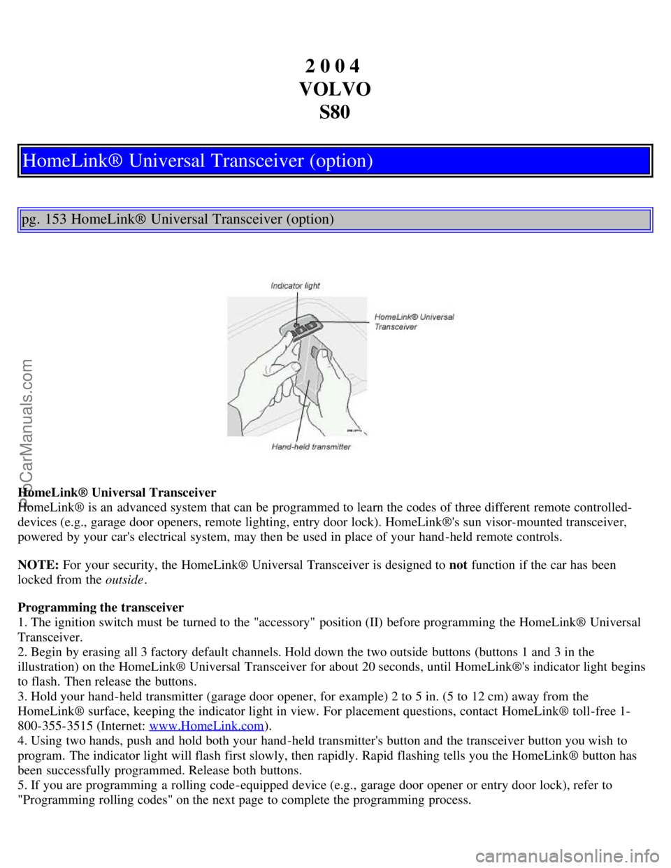
HomeLink® is an advanced system that can be programmed to learn the codes of three different remote controlled-
devices (e.g., garage door openers, remote lighting, entry door lock). HomeLink®'s sun visor-mounted transceiver,
powered by your car's electrical system, may then be used in place of your hand -held remote controls.
NOTE: For your security, the HomeLink® Universal Transceiver is designed to not function if the car has been
locked from the outside .
Programming the transceiver
1. The ignition switch must be turned to the "accessory" position (II) before programming the HomeLink® Universal
Transceiver.
2. Begin by erasing all 3 factory default channels. Hold down the two outside buttons (buttons 1 and 3 in the
illustration) on the HomeLink® Universal Transceiver for about 20 seconds, until HomeLink®'s indicator light begins
to flash. Then release the buttons.
3. Hold your hand -held transmitter (garage door opener, for example) 2 to 5 in. (5 to 12 cm) away from the
HomeLink® surface, keeping the indicator light in view. For placement questions, contact HomeLink® toll-free 1-
800-355-3515 (Internet: www.HomeLink.com
).
4. Using two hands, push and hold both your hand -held transmitter's button and the transceiver button you wish to
program. The indicator light will flash first slowly, then rapidly. Rapid flashing tells you the HomeLink® button has
been successfully programmed. Release both buttons.
5. If you are programming a rolling code-equipped device (e.g., garage door opener or entry door lock), refer to
"Programming rolling codes" on the next page to complete the programming process.
ProCarManuals.com
Page 98 of 110
programming the HomeLink® Universal Transceiver, call toll-free 1-800-355-3515 (Internet: www.HomeLink.com).
Operating the HomeLink® Universal Transceiver
Once programmed, the HomeLink® Universal Transceiver can be used in place of hand -held transmitters.
To operate, the key must be turned to the "accessory" position (II) or the engine must be running. Press the
programmed HomeLink® button to activate the garage door, driveway gate, security lighting, home security system,
etc.
Your original hand -held transmitters may, of course, be used at any time.
pg. 155 HomeLink® Universal Transceiver (option)
Erasing programmed buttons
Individual buttons cannot be erased. To erase all three programmed buttons:
1. Turn the ignition key to the "accessory" position (II).
2. Hold down the two outside buttons on the HomeLink® Universal Transceiver for about 20 seconds, until
HomeLink®'s indicator light begins to flash.
3. Release both buttons.
The HomeLink® buttons can be reprogrammed using the procedures described on the previous pages.
Reprogramming a single HomeLink® button
1. Press and hold the desired HomeLink® button. Do not release the button until step 3 has been completed.
2. When the indicator light begins to flash slowly (after approximately 20 seconds), position the hand -held transmitter
2 to 5 in. (5 to 12 cm) away from the HomeLink® surface.
3. Press and hold the hand -held transmitter button. The HomeLink® indicator light will flash first slowly, then rapidly.
When the indicator light flashes rapidly, release both buttons.
The previously programmed device has now been erased and the new device can be activated by pressing the
HomeLink® button that has just been programmed. This procedure will not affect any other programmed HomeLink®
buttons.
NOTE:
Retain the original transmitter(s) for future programming procedures (i.e., if you purchase a new car).
For your own security, erase all programmed buttons on the HomeLink® Universal Transceiver when you sell your
car.
Metallic sun protection films should not be used on any windows in a car equipped with HomeLink® Universal
Transceiver. This could interfere with the transceiver's function.
Contents | Top of Page
ProCarManuals.com