Page 49 of 99
, A, B, and C, representing the tires resistance to the generation of heat
and its ability to dissipate heat when tested under controlled conditions o")
The temperature grades are AA (the highest), A, B, and C, representing the tire's resistance to the generation of heat
and its ability to dissipate heat when tested under controlled conditions on a specified indoor laboratory test wheel.
Sustained high temperature can cause the material of the tire to degenerate and reduce tire life, and excessive
temperature can lead to sudden tire failure. The grade C corresponds to a minimum level of performance that all
passenger car tires must meet under the Federal Motor Safety Standard No. 109. Grades B and A represent higher
levels of performance on the laboratory test wheel than the minimum required by law.WARNING!
The temperature grade for this tire is established for a tire that is properly inflated and not overloaded. Excessive
speed, underinflation, or excessive loading, either separately or in combination, can cause heat buildup and possible
tire failure.
pg. 84 This page left intentionally blank
Contents | Top of Page
ProCarManuals.com
Page 50 of 99
2 0 0 4
VOLVO C70
Chapter 6 - In case of an emergency
pg. 85 In case of an emergency
Page
Wheel changing 86
Spare tire88
Replacing bulbs89
Replacing fuses95
Installation of accessories98
Replacing wiper blades99
In case of emergency101
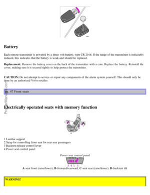
pg. 86 Wheel changing
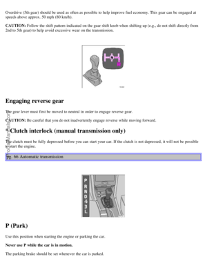
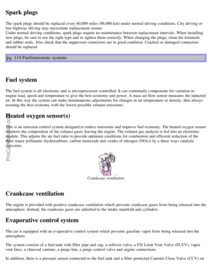
Loosen wheel bolts
Changing a wheel
The spare wheel is located under the carpet on the trunk floor. The jack and crank are secured in the wheel recess.
Engage the parking brake.
Put the gear selector in (P)ark (automatic) or in Reverse (manual).
With the car still on the ground, use the lug wrench to loosen the wheel bolts 1/2 - 1 turn. Turn the bolts
counterclockwise to loosen.
Fold out the crank handle on the jack by pressing the knob on the handle downward. To attach the jack, refer to the
ProCarManuals.com
Page 51 of 99

illustration on the following page.
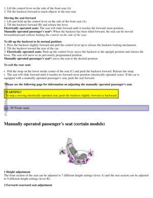
Jack attachment
There is a jack attachment located in the center on each side of the car. Position the jack on the bar in the attachment
as shown in illustration above and crank while simultaneously guiding the base of the jack to the ground. The base of
the jack must be flat on a level, firm, non-slippery surface. Before raising the car, check that the jack is still
correctly positioned in the attachment.
WARNING!
The jack's attachment must engage the bar in the jack attachment (see inset illustration above). The car's weight must
not rest on the jack attachment.
Raise the vehicle until both wheels on the side of the car where the jack is attached are lifted off the ground. Unscrew
the wheel bolts completely and carefully remove the wheel so as not to damage the thread on the studs.
NOTE: To avoid excessive wear and the necessity of rebalancing, mark and reinstall wheels in the same location and
position as before removal. To lessen the chance of imbalance, each wheel hub is equipped with a guide stud to ensure
that a removed wheel can be reinstalled in its original position (as when changing over to winter tires/wheels).
CAUTION: The car must not be driven with wheels of different dimensions or with a spare tire other than the one that
came with the car. The use of different size wheels can seriously damage your car's transmission.
pg. 87 Wheel changing
WARNING!
The jack's attachment must engage the bar in the jack attachment (see inset illustration in center column on the
previous page. The car's weight must not rest on the jack attachment.
Be sure the jack is on a firm, level, non-slippery surface.
Never allow any part of your body to be extended under a car supported by a jack.
Use the jack intended for the car when replacing a wheel. For any other job, use stands to support the side of the
car being worked on.
Apply the parking brake, select position P (automatic transmission) or Reverse gear (manual transmission).
Block the wheels standing on the ground, use rigid wooden blocks or large stones.
The jack should be kept well-greased.
Installing the wheel
ProCarManuals.com
Page 52 of 99

Clean the contact surfaces on the wheel and hub. Lift the wheel and place it on the hub. Make sure that you align the
wheel with the guide stud on the wheel hub prior to installation. Install the wheel bolts crosswise (see illustration) and
tighten by turning lightly clockwise. Lower the vehicle to the ground and alternately tighten the bolts to 100 ft. lbs.
(130 Nm). Install the wheel cap (where applicable).
CAUTION: Correct tightening torque on wheel bolts must be observed. The wheel bolts should never be greased or
lubricated. The extended, chromed wheel bolts must not be used with steel rims, as they make it impossible to fit the
hub caps.
Correct tightening order for wheel bolts
pg. 88 Spare tire
Temporary Spare (certain models)
The spare tire in your car is called a "Temporary Spare". It has the following designation: T125/90 R15.
Recommended tire pressure (see decal on fuel filler flap) should be maintained irrespective of which position on the
car the Temporary Spare tire is used on.
In the event of damage to this tire, a new one can be purchased from your Volvo retailer.
CAUTION: The car must not be driven with wheels of different dimensions or with a spare tire other than the one that
came with the car. The use of different size wheels can seriously damage your car's transmission.
WARNING!
Current legislation prohibits the use of the "Temporary Spare" tire other than as a temporary replacement for a
punctured tire. In other words, it must be replaced as soon as possible by a standard tire. Roadholding, etc., may be
affected with the "Temporary Spare" in use. Do not, therefore, exceed 50 mph (80 km/h).
pg. 89 Replacing bulbs
ProCarManuals.com
Page 53 of 99
Parking light/direction indicator
1. From the front of the car, use a screwdriver to press down on the silver catch (located in the space between the
inside of the fender and the headlight unit) to release the lamp housing from the front fender.
2. Turn the bulb holder 1/4 turn clockwise (viewed from the front) and withdraw it from the from the lamp housing.
Leave the connector with its wires in the bulb holder.
4. Remove the bulb from the holder by pulling it straight out.
5. Press a new bulb into the holder and reinstall the unit in the reverse order.
Side direction indicator
1. Slide the lens forward and pull out the rear edge.
2. Pull out the entire lens/bulb unit.
3. With the lens toward you, turn the bulb holder 1/4 turn (the wires should not be disconnected from the holder) and
pull out the bulb holder from the lens unit.
ProCarManuals.com
Page 54 of 99
 - H7 B - High")
4. Pull the old bulb straight out and press a new one into place.
5. Replace the entire unit in the reverse order.
pg. 90 Replacing bulbs
A - Low beam Bulbs (high and low beams) - H7 B - High beam
Low beam headlight bulb (A) replacement
1. Turn the plastic cover counterclockwise and remove it.
2. Press the wire catches on the retaining clamp (1 in inset illustration above) together and push out (2) to release the
bulb and connector from the headlight housing.
3. Pull the bulb out of the connector.
4. Insert a new bulb into the connector.
5. Reinsert the bulb and connector into the headlight housing. The guide lug must be up to ensure proper positioning.
6. Press the retaining clamp back into position.
7. Reinstall the plastic cover. The marking "Top" on the cover should be up when the cover is reinstalled.
High beam headlight bulb (B) replacement
1. Pull the catch on the lower edge of the cover upward and remove the plastic cover.
2. Press the wire catches on the retaining clamp (1 in inset illustration above) together and push out (2) to release the
bulb and connector from the headlight housing.
3. Pull the bulb out of the connector.
4. Insert a new bulb into the connector.
5. Reinsert the bulb and connector into the headlight housing. The guide lug must be up to ensure proper positioning.
6. Press the retaining clamp back into position.
7. Reinstall the plastic cover. Catch B should snap into position.
Caution:
Do not touch the glass on halogen bulbs with your fingers. Grease, oil or any other impurities can be carbonized onto
the bulb and cause damage to the reflector.
Be sure to use bulbs of the correct type and voltage.
ProCarManuals.com
Page 55 of 99
pg. 91 Replacing bulbs
Tail light bulbs
1. Tail light
2. Direction indicator
3. Brake light
4. Tail light
5. Back-up light
6. Rear fog light (left side only)
All the bulbs in the tail light unit are replaced from inside the trunk as follows:
1. Turn the plastic screw and remove the cover over the rear lamp unit.
2. Remove the wing nut and remove the bulb holder.
3. Let the connector with its wires remain attached to the bulb holder.
4. Remove the bulb by pressing in and turning counterclockwise.
5. Insert a new bulb into the holder and reinstall the holder into the tail light assembly.
6. Close the cover.
pg. 92 Replacing bulbs
Insert screwdriver and turn
ProCarManuals.com
Page 56 of 99
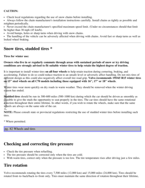
Trunk light
1. Switch off the lights.
2. Press in the catch with a screwdriver and remove the bulb holder.
3. Replace the bulb and reinstall the bulb holder.
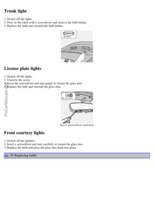
License plate lights
1. Switch off the lights.
2. Unscrew the screw.
3. Insert the screwdriver and turn gently to loosen the glass lens.
4. Replace the bulb and reinstall the glass lens.
Insert screwdriver and turn
Front courtesy lights
1. Switch off the ignition.
2. Insert a screwdriver and turn carefully to loosen the glass lens.
3. Replace the bulb and press the glass lens back into place.
pg. 93 Replacing bulbs
ProCarManuals.com


")

All the bulbs in the tail light unit")
