Page 113 of 136
A62964
A62965
A62966
A62967
Free
Lock 19±12
± STARTING & CHARGINGSTARTER ASSY(2.0KW) (1CD±FTV)
1CD±FTV ENGINE REPAIR MANUAL (RM927E)
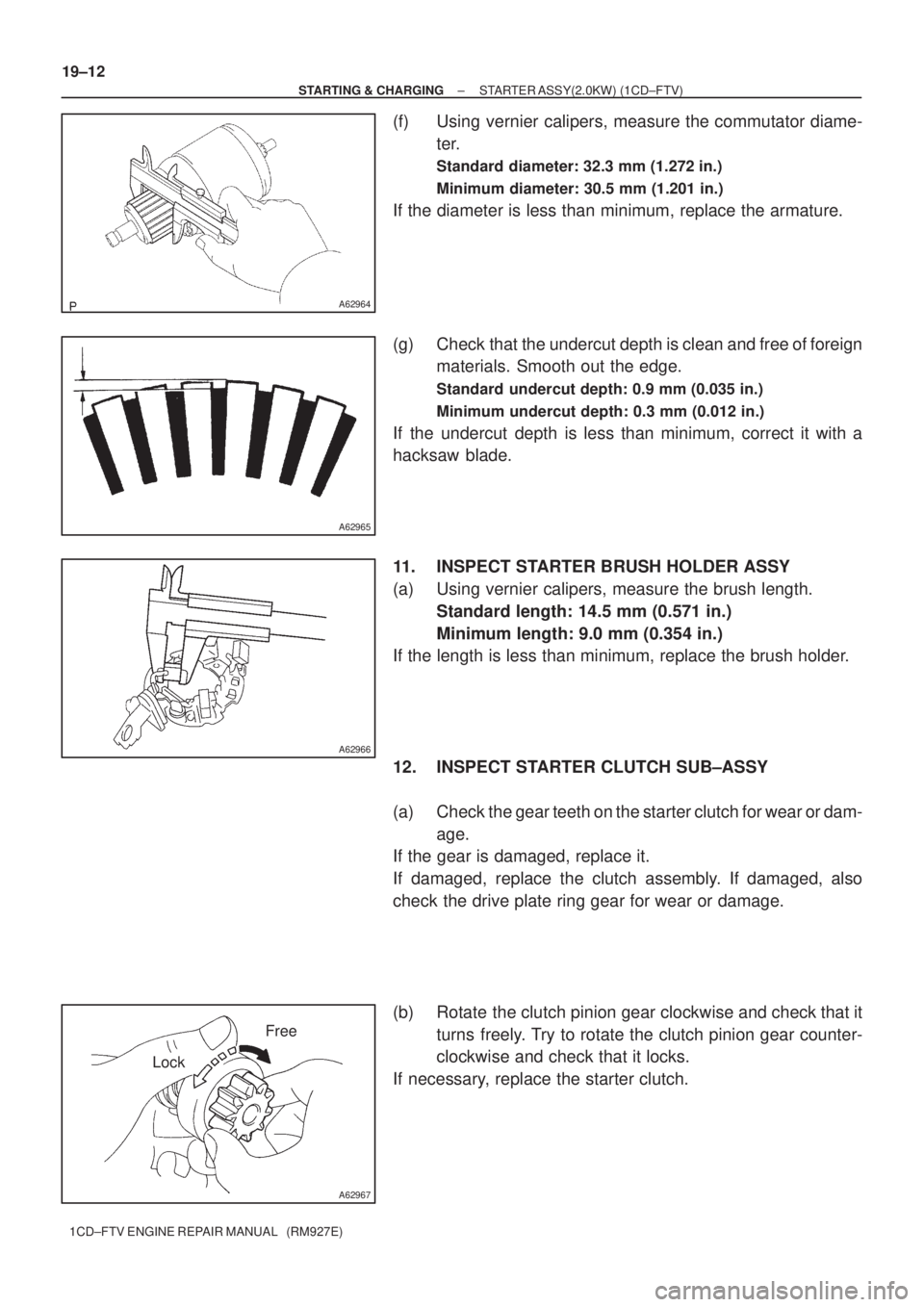
(f) Using vernier calipers, measure the commutator diame-
ter.
Standard diameter: 32.3 mm (1.272 in.)
Minimum diameter: 30.5 mm (1.201 in.)
If the diameter is less than minimum, replace the armature.
(g) Check that the undercut depth is clean and free of foreign
materials. Smooth out the edge.
Standard undercut depth: 0.9 mm (0.035 in.)
Minimum undercut depth: 0.3 mm (0.012 in.)
If the undercut depth is less than minimum, correct it with a
hacksaw blade.
11. INSPECT STARTER BRUSH HOLDER ASSY
(a) Using vernier calipers, measure the brush length.
Standard length: 14.5 mm (0.571 in.)
Minimum length: 9.0 mm (0.354 in.)
If the length is less than minimum, replace the brush holder.
12. INSPECT STARTER CLUTCH SUB±ASSY
(a) Check the gear teeth on the starter clutch for wear or dam-
age.
If the gear is damaged, replace it.
If damaged, replace the clutch assembly. If damaged, also
check the drive plate ring gear for wear or damage.
(b) Rotate the clutch pinion gear clockwise and check that it
turns freely. Try to rotate the clutch pinion gear counter-
clockwise and check that it locks.
If necessary, replace the starter clutch.
Page 121 of 136
A51187
A51188
A55639
A55640
A55641
19±20
± STARTING & CHARGINGSTARTER ASSY(2.2KW) (1CD±FTV)
1CD±FTV ENGINE REPAIR MANUAL (RM927E)
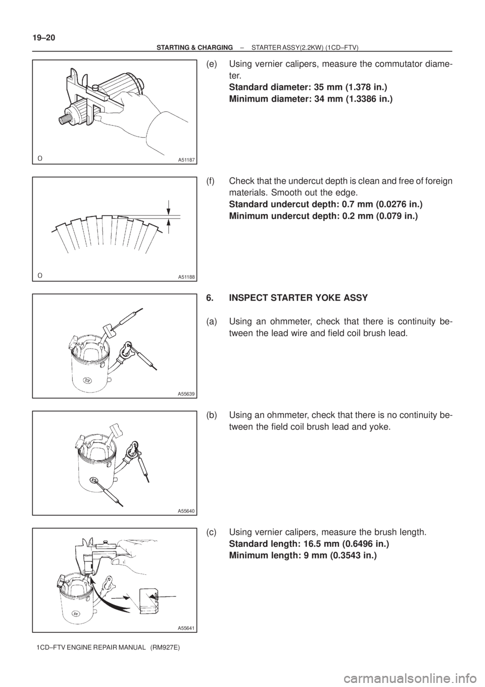
(e) Using vernier calipers, measure the commutator diame-
ter.
Standard diameter: 35 mm (1.378 in.)
Minimum diameter: 34 mm (1.3386 in.)
(f) Check that the undercut depth is clean and free of foreign
materials. Smooth out the edge.
Standard undercut depth: 0.7 mm (0.0276 in.)
Minimum undercut depth: 0.2 mm (0.079 in.)
6. INSPECT STARTER YOKE ASSY
(a) Using an ohmmeter, check that there is continuity be-
tween the lead wire and field coil brush lead.
(b) Using an ohmmeter, check that there is no continuity be-
tween the field coil brush lead and yoke.
(c) Using vernier calipers, measure the brush length.
Standard length: 16.5 mm (0.6496 in.)
Minimum length: 9 mm (0.3543 in.)
Page 122 of 136
A55642
A55643
A55624
Free
Lock
B55687
Terminal 50
Terminal C
B55691
Terminal 50
Switch Body
± STARTING & CHARGINGSTARTER ASSY(2.2KW) (1CD±FTV)
19±21
1CD±FTV ENGINE REPAIR MANUAL (RM927E)
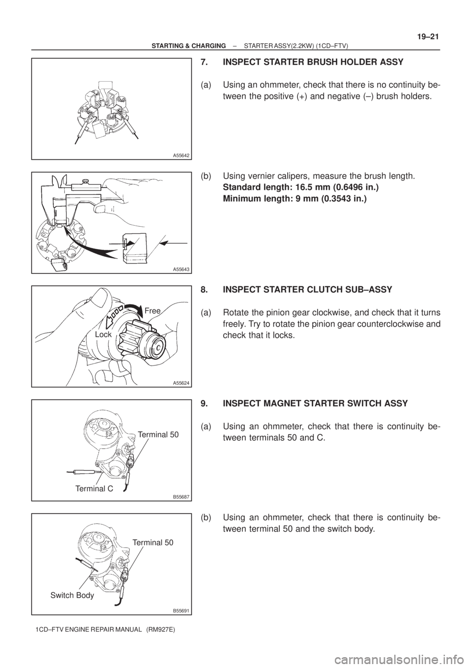
7. INSPECT STARTER BRUSH HOLDER ASSY
(a) Using an ohmmeter, check that there is no continuity be-
tween the positive (+) and negative (±) brush holders.
(b) Using vernier calipers, measure the brush length.
Standard length: 16.5 mm (0.6496 in.)
Minimum length: 9 mm (0.3543 in.)
8. INSPECT STARTER CLUTCH SUB±ASSY
(a) Rotate the pinion gear clockwise, and check that it turns
freely. Try to rotate the pinion gear counterclockwise and
check that it locks.
9. INSPECT MAGNET STARTER SWITCH ASSY
(a) Using an ohmmeter, check that there is continuity be-
tween terminals 50 and C.
(b) Using an ohmmeter, check that there is continuity be-
tween terminal 50 and the switch body.
Page 129 of 136
Length
P13535
17 mm
Socket
Wrench
A51920
Cord ClipA
B
A A
A64533
Inside
A51921
19±28
± STARTING & CHARGINGGENERATOR ASSY(90A) (1CD±FTV)
1CD±FTV ENGINE REPAIR MANUAL (RM927E)
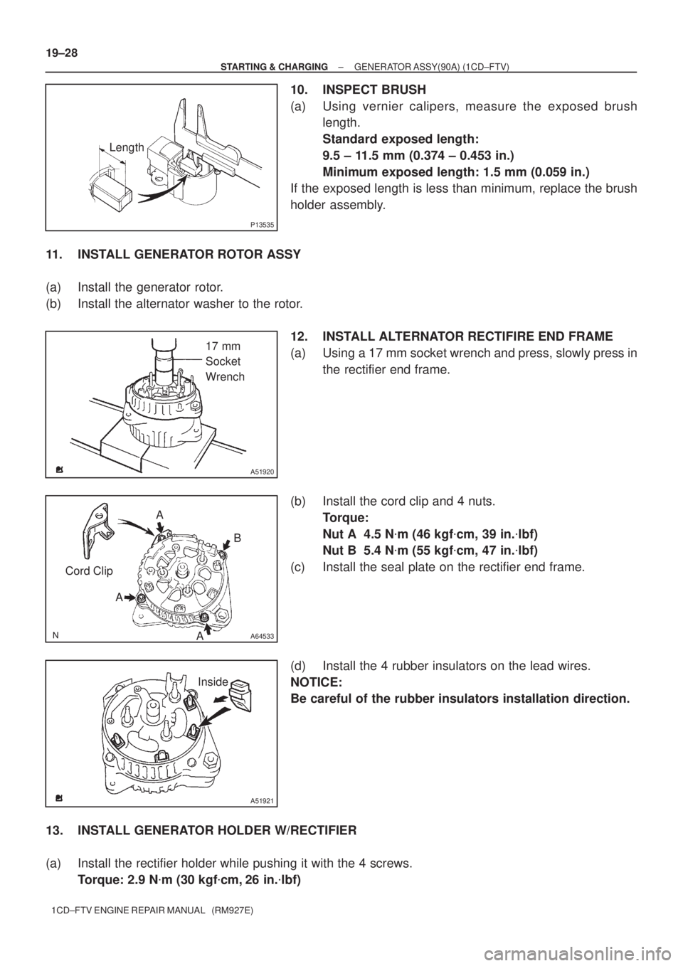
10. INSPECT BRUSH
(a) Using vernier calipers, measure the exposed brush
length.
Standard exposed length:
9.5 ± 11.5 mm (0.374 ± 0.453 in.)
Minimum exposed length: 1.5 mm (0.059 in.)
If the exposed length is less than minimum, replace the brush
holder assembly.
11. INSTALL GENERATOR ROTOR ASSY
(a) Install the generator rotor.
(b) Install the alternator washer to the rotor.
12. INSTALL ALTERNATOR RECTIFIRE END FRAME
(a) Using a 17 mm socket wrench and press, slowly press in
the rectifier end frame.
(b) Install the cord clip and 4 nuts.
Torque:
Nut A 4.5 N�m (46 kgf�cm, 39 in.�lbf)
Nut B 5.4 N�m (55 kgf�cm, 47 in.�lbf)
(c) Install the seal plate on the rectifier end frame.
(d) Install the 4 rubber insulators on the lead wires.
NOTICE:
Be careful of the rubber insulators installation direction.
13. INSTALL GENERATOR HOLDER W/RECTIFIER
(a) Install the rectifier holder while pushing it with the 4 screws.
Torque: 2.9 N�m (30 kgf�cm, 26 in.�lbf)
Page 135 of 136
A57799
A57800
A57801
A57802
Socket
Wrench
(29 mm)
A57795
19±34
± STARTING & CHARGINGGENERATOR ASSY(130A) (1CD±FTV)
1CD±FTV ENGINE REPAIR MANUAL (RM927E)
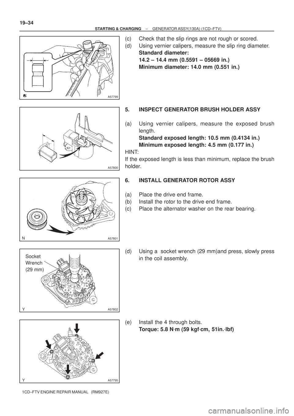
(c) Check that the slip rings are not rough or scored.
(d) Using vernier calipers, measure the slip ring diameter.
Standard diameter:
14.2 ± 14.4 mm (0.5591 ± 05669 in.)
Minimum diameter: 14.0 mm (0.551 in.)
5. INSPECT GENERATOR BRUSH HOLDER ASSY
(a) Using vernier calipers, measure the exposed brush
length.
Standard exposed length: 10.5 mm (0.4134 in.)
Minimum exposed length: 4.5 mm (0.177 in.)
HINT:
If the exposed length is less than minimum, replace the brush
holder.
6. INSTALL GENERATOR ROTOR ASSY
(a) Place the drive end frame.
(b) Install the rotor to the drive end frame.
(c) Place the alternator washer on the rear bearing.
(d) Using a socket wrench (29 mm)and press, slowly press
in the coil assembly.
(e) Install the 4 through bolts.
Torque: 5.8 N�m (59 kgf�cm, 51in.�lbf)
Page 136 of 136
A55650
SST (A)
SST (B)
A55651
Rotor Shaft
SST (A)
A57803
SST (B)
Turn
A57804
Upward
A55648
± STARTING & CHARGINGGENERATOR ASSY(130A) (1CD±FTV)
19±35
1CD±FTV ENGINE REPAIR MANUAL (RM927E)
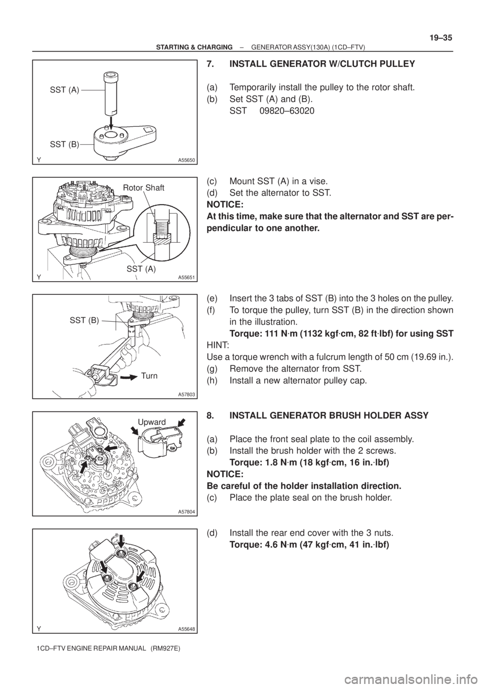
7. INSTALL GENERATOR W/CLUTCH PULLEY
(a) Temporarily install the pulley to the rotor shaft.
(b) Set SST (A) and (B).
SST 09820±63020
(c) Mount SST (A) in a vise.
(d) Set the alternator to SST.
NOTICE:
At this time, make sure that the alternator and SST are per-
pendicular to one another.
(e) Insert the 3 tabs of SST (B) into the 3 holes on the pulley.
(f) To torque the pulley, turn SST (B) in the direction shown
in the illustration.
Torque: 111 N�m (1132 kgf�cm, 82 ft�lbf) for using SST
HINT:
Use a torque wrench with a fulcrum length of 50 cm (19.69 in.).
(g) Remove the alternator from SST.
(h) Install a new alternator pulley cap.
8. INSTALL GENERATOR BRUSH HOLDER ASSY
(a) Place the front seal plate to the coil assembly.
(b) Install the brush holder with the 2 screws.
Torque: 1.8 N�m (18 kgf�cm, 16 in.�lbf)
NOTICE:
Be careful of the holder installation direction.
(c) Place the plate seal on the brush holder.
(d) Install the rear end cover with the 3 nuts.
Torque: 4.6 N�m (47 kgf�cm, 41 in.�lbf)