Page 183 of 491

3-46
Instruments and controls
detect it and make the reflection surface of the mirror
dimmer to help prevent you from being blinded. For
this reason, use care not to cover the sensors with
stickers, or other similar items. Periodically wipe the
sensors clean using a piece of dry soft cotton cloth or
an applicator. "
Compass calibration
1. For optimum calibration, switch off all nonessential
electrical accessories (rear window defogger, heater/
air conditioning system, spotlight, etc.) and ensure all
doors are shut.
2. Drive to an open, level area away from large metal-
lic objects or structures and make certain the ignition
switch is in the “ON” position.
3. Press and hold the left button for 3 seconds then re-
lease, and the compass will enter the calibration
mode. “CAL” and direction will be displayed.
4. Drive slowly in a circle until “CAL” disappears from
the display (about two or three circles). The compass
is now calibrated.
5. Further calibration may be necessary should out-
side. Influences cause the mirror to read inaccurately.
You will know that this has occurred if your compass
begins to read in only limited directions. Should you
encounter this situation, return to step one of the
above procedure and recalibrate the mirror. "
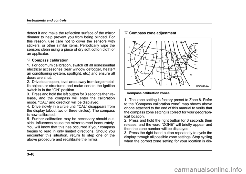
Compass zone adjustment
Compass calibration zones
1. The zone setting is factory preset to Zone 8. Refer
to the “Compass calibration zone” map shown above
or one attached to the end of this manual to verify that
the compass zone setting is correct for your geograph-ical location.
2. Press and hold the right button for 3 seconds then
release, and the word “ZONE” will briefly appear and
then the zone number will be displayed.
3. Press the right hand button repeatedly to cycle the
display through all possible zone settings. Stop cycling
when the correct zone setting for your location is dis-
10
9
8
7
6
5
4
3
1112
13
HGF048AA
Page 184 of 491
3-47
Instruments and controls
– CONTINUED –
played.
4. Releasing the button for 3 seconds will exit the
zone setting mode. !Outside mirrors
! Convex mirror (passenger side)
Objects look smaller in a convex mirror and far-
ther away than when viewed in a flat mirror. Do
not use the convex mirror to judge the distance
of vehicles behind you when changing lanes.
Use the inside mirror (or glance backwards) to determine the actual size and distance of ob-
jects that you view in convex mirror.
! Remote control mirror switch
1) Selection switch
2) Direction control switch
The remote control mirrors operate only when the ig-
nition switch is in the “ON” or “ACC” position.
1. Press either end of the selection switch, “L” for the left, “R” for the right.
2. Move the direction control switch in the direction
you want to move the mirror.
HS3040BA
1
2
UG3510BB
Page 185 of 491
3-48
Instruments and controls
3. Return the selection switch to the neutral position
to prevent unintentional operation.
The mirrors can also be adjusted manually. !
Outside mirror defogger (if equipped)
Manual climate control system Semi-automatic climate control system
The outside mirror defogger shares the switch with
rear window defogger.
The outside mirror defogger operates only when the
ignition switch is in the “ON” position.
To turn on the outside mirror defogger, push the
switch. To turn it off, push the switch again. The indi-
cator light located on the switch lights up while the out-
side mirror defogger is operating.
The defogger will automatically shut off after about 15
minutes. If the mirror clears before that time, push the
switch to turn it off. It also turns off when the ignition
switch is turned to the “ACC” or “LOCK” position. If de-
UG3508BA
UG3035BA
Page 186 of 491
3-49
Instruments and controls
– CONTINUED –
frosting or defogging is desired when you restart your
vehicle, you have to push the switch to turn it on again.
NOTE
While the outside mirror defogger is operating, the
rear window defogger also operates.
To prevent the battery from being discharged,
do not operate the defogger continuously for
any longer than necessary.
Tilt steering wheel
1. Adjust the seat position. Refer to the “Front seats”
section (chapter 1).
2. Push the tilt lock lever down.
3. Move the steering wheel to the desired level.
4. Pull the lever up to lock the steering wheel in place.
5. Make sure that the steering wheel is securely
locked by moving it up and down.
Do not adjust the steering wheel tilt position
while driving. This may cause loss of vehicle
HS3043BA
Page 250 of 491

6-1
6
Interior equipment
In te ri or lig ht ..... ... ... .. ... ... ... ... ... .. ... ... ... ... .. ... ... 6-2
D om e lig ht ............ ..................... ..................... ... 6-2
C argo are a lig ht (if eq uip ped) ....................... ... 6-2
Map li g h t (if e qui pp ed ) ..... ... ... .. ... ... ... ... .. ... ... 6-3
Sun visors .. ... ... ... ... .. ... ... ... ... ... .. ... ... ... ... .. ... ... 6-4
Center visor ....................................................... 6-4
Vanity mirror (if equipped) ............................... 6-5
Storage com partments .... ... ... .. ... ... ... ... .. ... ... 6-5
Gl ove b ox .............. ..................... ..................... ... 6-6
C enter con sole .......................... ..................... ... 6-6
C oin tray ............... ..................... ..................... ... 6-7
C up h older .... ... ... ... .. ... ... ... ... ... .. ... ... ... ... .. ... ... 6-7
In in stru ment pa nel ................... ..................... ... 6-7
In ce nter co nsole .. .................... ..................... ... 6-8
A cce sso ry p ow er o utlet ............................... 6-9
In t h e cargo area (if eq uip ped) .. .................... ... 6-9
C ig are tte lig hter so cket ................................ 6-10
U se with a cigarette li ght er ...... ..................... ... 6-11
U sing as an access ory power o utlet ............ ... 6-11
As htray .. ... .. ... ... ... ... .. ... ... ... ... ... .. ... ... ... ... .. ... ... 6-12
Fl oo r mat (if e qui pp ed ) .. ... ... ... .. ... ... ... ... .. ... ... 6-13
C oat hook ... ... ... ... ... .. ... ... ... ... ... .. ... ... ... ... .. ... ... 6-14
Cargo area c over ( if eq uip p ed) ... ... ... ... .. ... ... 6-15
U sing t h e cover .... ..................... ..................... ... 6-15
T o re move the c over ................. ..................... ... 6-15
Stowage of the c over ................ ..................... ... 6-16
T o in stall the co ver housi ng .... ..................... ... 6-16
Cargo tie-down hooks (if equipped) ........... 6-17 Under-floor storage compartment
(if equipped) ............................................... 6-18
Page 254 of 491
6-5
Interior equipment
– CONTINUED –
!Vanity mirror (if equipped)
To use the vanity mirror, swing down the sun visor and
open the vanity mirror cover.Storage compartments
" Always keep the storage compartment
closed while driving to reduce the risk of injury
in the event of sudden stops or an accident." Do not store spray cans, containers with
flammable or corrosive liquids or any other
dangerous items in the storage compartment.
HG6017BA
Page 278 of 491

7-9
Starting and operating
– CONTINUED –
Preparing to drive
You should perform the following checks and adjust-
ments every day before you start driving.
1. Check that all windows, mirrors, and lights are
clean and unobstructed.
2. Check the appearance and condition of the tires.
Also check tires for proper inflation.
3. Look under the vehicle for any sign of leaks.
4. Check that the hood, trunk and rear gate are fully
closed.
5. Check the adjustment of the seat.
6. Check the adjustment of the inside and outside mir-
rors.
7. Fasten your seatbelt. Check that your passengers
have fastened their seatbelts.
8. Check the operation of the warning and indicator
lights when the ignition switch is turned to the “ON” po-sition.
9. Check the gauges, indicator and warning lights af-
ter starting the engine.
NOTE
Engine oil, engine coolant, brake fluid, washer flu-
id and other fluid levels should be checked daily,
weekly or at fuel stops.
Starting the engine
Do not operate the starter motor continuously
for more than ten seconds. If the engine fails to
start after operating the starter for five to ten
seconds, wait for ten seconds or more before
trying again.
! Manual transmission vehicle
1. Apply the parking brake.
2. Turn off unnecessary lights and accessories.
3. Press the clutch pedal to the floor and shift the shift
lever into neutral. Hold the clutch pedal to the floor
while starting the engine.
The starter motor will only operate when the clutch
pedal is pressed fully to the floor.
4. Turn the ignition switch to the “ON” position and
check the operation of the warning and indicator lights.
Refer to the “Warning and indicator lights” section (chapter 3).
5. Turn the ignition switch to the “START” position
without depressing the accelerator pedal. Release
the key immediately after the engine has started.
Page 347 of 491

8-36
Driving tips
"
Adequate size trailer brakes are required
when the trailer and its cargo exceed 1,000 lbs
(453 kg) total weight." Do not directly connect your trailer’s hydrau-
lic brake system to the hydraulic brake system
in your vehicle. Direct connection would cause
the vehicle’s brake performance to deteriorate
and could lead to an accident.
! Trailer safety chains
In case the trailer hitch connector or hitch ball should
break or become disconnected, the trailer could get
loose and create a traffic safety hazard.
For safety, always connect the towing vehicle and
trailer with trailer safety chains. Pass the chains cross-
ing each other under the trailer tongue to prevent the
trailer from dropping onto the ground in case the trailer
tongue should disconnect from the hitch ball. Allow
sufficient slack in the chains taking tight-turn situations
into account; however, be careful not to let them drag
on the ground.
For more information about the safety chain connec-
tion, refer to the instructions for your hitch and trailer.
Always use safety chains between your vehicle
and the trailer. Towing a trailer without safety
chains could create a traffic safety hazard if the
trailer separates from the hitch due to coupling
damage or hitch ball damage.
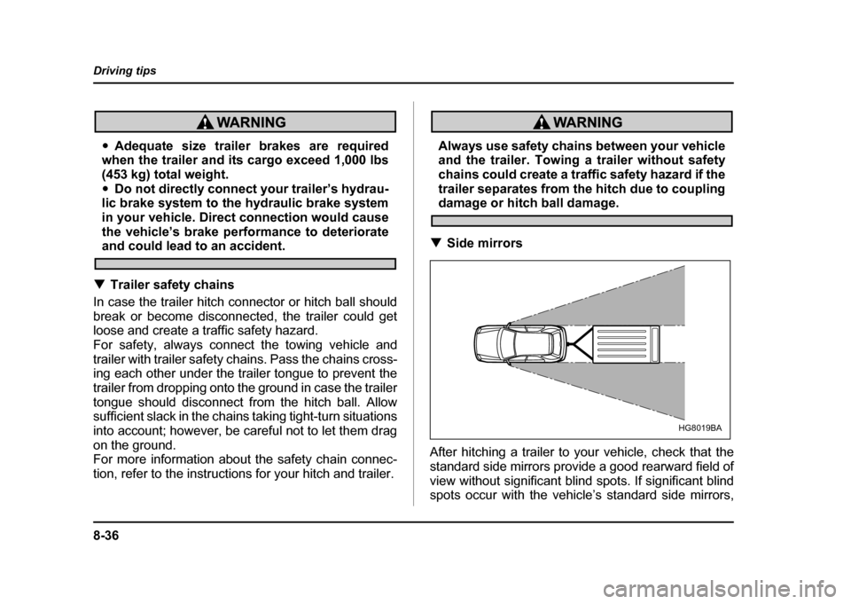
! Side mirrors
After hitching a trailer to your vehicle, check that the
standard side mirrors provide a good rearward field of
view without significant blind spots. If significant blind
spots occur with the vehicle’s standard side mirrors,
HG8019BA