Page 779 of 2870

PM-42
PERIODIC MAINTENANCE SERVICE
Steering System (Power Steering)
(2) Retighten the adjusting screw to 7.4 N·m
(0.75 kgf-m, 5.4 ft-lb) and back off 25°.
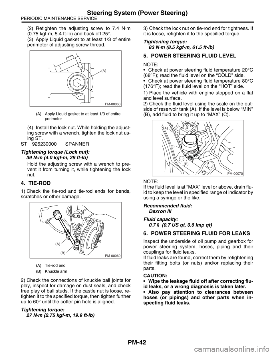
(3) Apply Liquid gasket to at least 1/3 of entire
perimeter of adjusting screw thread.
(4) Install the lock nut. While holding the adjust-
ing screw with a wrench, tighten the lock nut us-
ing ST.
ST 926230000 SPANNER
Tightening torque (Lock nut):
39 N·m (4.0 kgf-m, 29 ft-lb)
Hold the adjusting screw with a wrench to pre-
vent it from turning it, while tightening the lock
nut.
4. TIE-ROD
1) Check the tie-rod and tie-rod ends for bends,
scratches or other damage.
2) Check the connections of knuckle ball joints for
play, inspect for damage on dust seals, and check
free play of ball studs. If the castle nut is loose, re-
tighten it to the specified torque, then tighten further
up to 60° until the cotter pin hole is aligned.
Tightening torque:
27 N·m (2.75 kgf-m, 19.9 ft-lb)3) Check the lock nut on tie-rod end for tightness. If
it is loose, retighten it to the specified torque.
Tightening torque:
83 N·m (8.5 kgf-m, 61.5 ft-lb)
5. POWER STEERING FLUID LEVEL
NOTE:
Check at power steering fluid temperature 20°C
(68°F); read the fluid level on the “COLD” side.
Check at power steering fluid temperature 80°C
(176°F); read the fluid level on the “HOT” side.
1) Place the vehicle with engine stopped on a flat
and level surface.
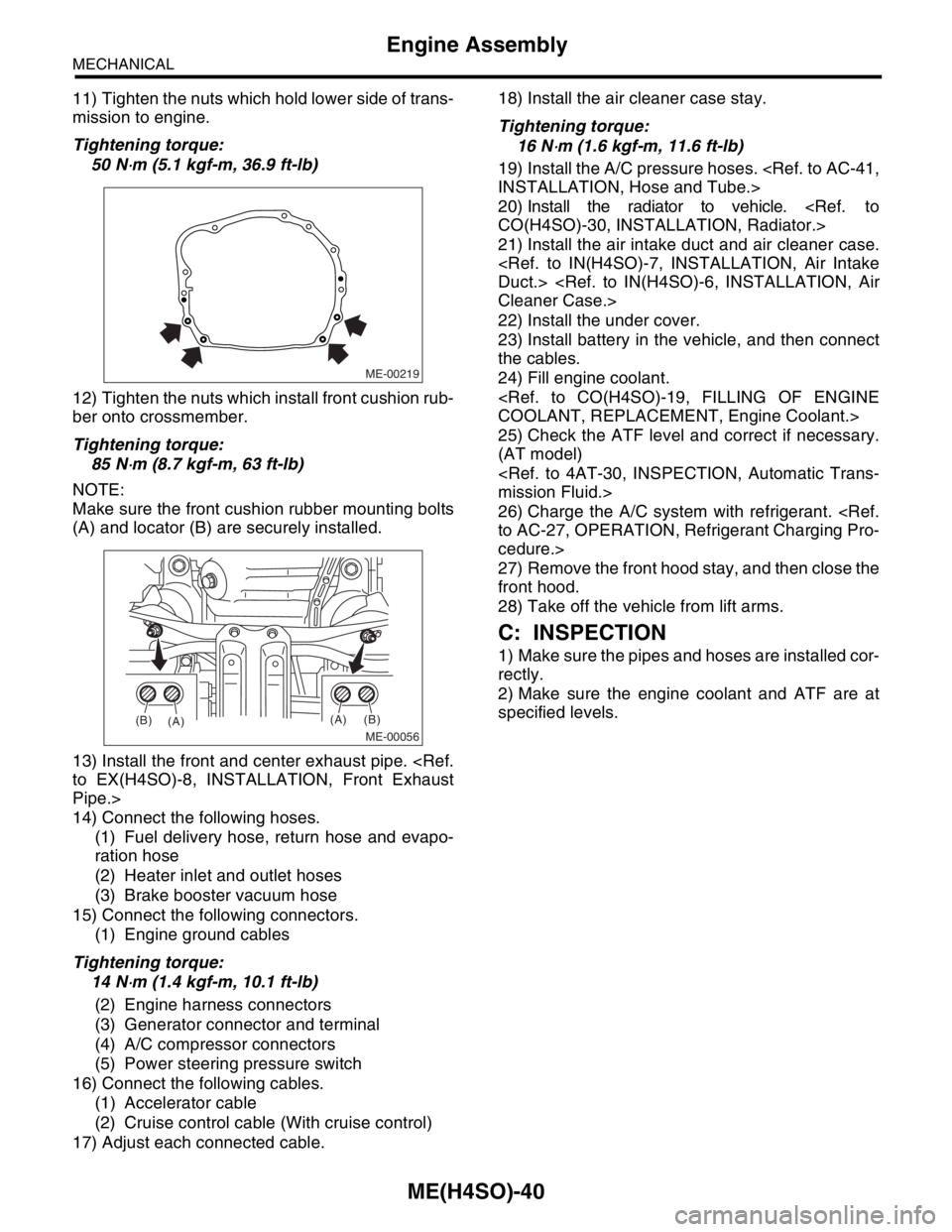
2) Check the fluid level using the scale on the out-
side of reservoir tank (A). If the level is below “MIN”
(B), add fluid to bring it up to “MAX” (C).
NOTE:
If the fluid level is at “MAX” level or above, drain flu-
id to keep the level in specified range of indicator by
using a syringe or the like.
Recommended fluid:
Dexron III
Fluid capacity:
0.72 (0.7 US qt, 0.6 Imp qt)
6. POWER STEERING FLUID FOR LEAKS
Inspect the underside of oil pump and gearbox for
power steering system, hoses, piping and their
couplings for fluid leaks.
If fluid leaks are found, correct them by retightening
their fitting bolts (or nuts) and/or replacing their
parts.
CAUTION:
Wipe the leakage fluid off after correcting flu-
id leaks, or a wrong diagnosis is taken later.
Also pay attention to clearances between
hoses (or pipings) and other parts when in-
specting fluid leaks.
(A) Apply Liquid gasket to at least 1/3 of entire
perimeter
(A) Tie-rod end
(B) Knuckle arm
PM-00068
(A)
PM-00069
(A)
(B)
PM-00070
(A)
(C)
(B)
Page 909 of 2870

ME(H4SO)-40
MECHANICAL
Engine Assembly
11) Tighten the nuts which hold lower side of trans-
mission to engine.
Tightening torque:
50 N
⋅m (5.1 kgf-m, 36.9 ft-lb)
12) Tighten the nuts which install front cushion rub-
ber onto crossmember.
Tightening torque:
85 N
⋅m (8.7 kgf-m, 63 ft-lb)
NOTE:
Make sure the front cushion rubber mounting bolts
(A) and locator (B) are securely installed.
13) Install the front and center exhaust pipe.
to EX(H4SO)-8, INSTALLATION, Front Exhaust
Pipe.>
14) Connect the following hoses.
(1) Fuel delivery hose, return hose and evapo-
ration hose
(2) Heater inlet and outlet hoses
(3) Brake booster vacuum hose
15) Connect the following connectors.
(1) Engine ground cables
Tightening torque:
14 N
⋅m (1.4 kgf-m, 10.1 ft-lb)
(2) Engine harness connectors
(3) Generator connector and terminal
(4) A/C compressor connectors
(5) Power steering pressure switch
16) Connect the following cables.
(1) Accelerator cable
(2) Cruise control cable (With cruise control)
17) Adjust each connected cable.18) Install the air cleaner case stay.
Tightening torque:
16 N
⋅m (1.6 kgf-m, 11.6 ft-lb)
19) Install the A/C pressure hoses.
INSTALLATION, Hose and Tube.>
20) Install the radiator to vehicle.
CO(H4SO)-30, INSTALLATION, Radiator.>
21) Install the air intake duct and air cleaner case.
Duct.>
Cleaner Case.>
22) Install the under cover.
23) Install battery in the vehicle, and then connect
the cables.
24) Fill engine coolant.
COOLANT, REPLACEMENT, Engine Coolant.>
25) Check the ATF level and correct if necessary.
(AT model)
mission Fluid.>
26) Charge the A/C system with refrigerant.
to AC-27, OPERATION, Refrigerant Charging Pro-
cedure.>
27) Remove the front hood stay, and then close the
front hood.
28) Take off the vehicle from lift arms.
C: INSPECTION
1) Make sure the pipes and hoses are installed cor-
rectly.
2) Make sure the engine coolant and ATF are at
specified levels.
ME-00219
ME-00056
(A)
(A)(B)
(B)
Page 1014 of 2870
CO(H4SO)-31
COOLING
Radiator
4) Attach the power steering hose to radiator.
5) Connect the radiator inlet hose.
6) Install the reservoir tank.
Tightening torque:
4.9 N
⋅m (0.50 kgf-m, 3.6 ft-lb)
7) Connect the overflow hose.
8) Lift-up the vehicle.
9) Connect the ATF cooler hoses. (AT model)10) Connect the radiator outlet hose.
11) Connect the connectors to radiator main fan
motor (A) and sub fan motor (B).
12) Install the under cover.
13) Lower the vehicle.
14) Connect the battery ground cable to battery.
15) Fill engine coolant.
FILLING OF ENGINE COOLANT, REPLACE-
MENT, Engine Coolant.>
16) Check the ATF level.
SPECTION, Automatic Transmission Fluid.>
CO-00037
CO-00035
CO-00015
CO-00034
CO-00076
CO-00013
(A)(B)
FU-00009