2004 SUBARU FORESTER oil
[x] Cancel search: oilPage 38 of 2870
AC-36
HVAC SYSTEM (HEATER, VENTILATOR AND A/C)
Compressor
11.Compressor
A: INSPECTION
1. MAGNETIC CLUTCH CLEARANCE
1) Check the clearance of the entire circumference
around the drive plate and pulley.
Standard:
0.3 — 0.6 mm (0.0118 — 0.0236 in)
2. MAGNETIC CLUTCH OPERATION
1) Disconnect the compressor connector.
2) Connect the battery positive (+) terminal to the
No. 3 terminal of the compressor connector.
3) Make sure the magnet clutch engages.
If NG, replace the compressor.
B: REMOVAL
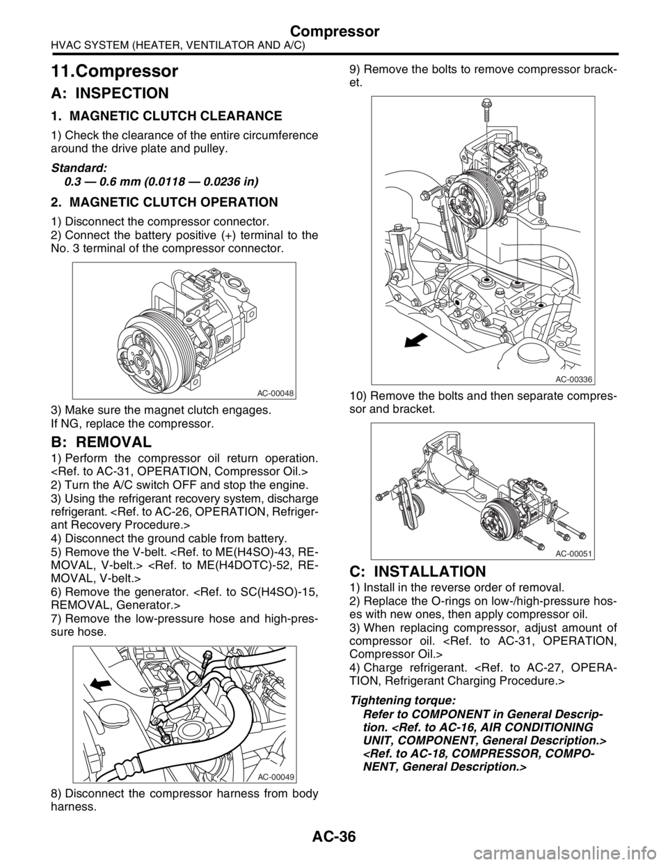
1) Perform the compressor oil return operation.
2) Turn the A/C switch OFF and stop the engine.
3) Using the refrigerant recovery system, discharge
refrigerant.
4) Disconnect the ground cable from battery.
5) Remove the V-belt.
6) Remove the generator.
7) Remove the low-pressure hose and high-pres-
sure hose.
8) Disconnect the compressor harness from body
harness.9) Remove the bolts to remove compressor brack-
et.
10) Remove the bolts and then separate compres-
sor and bracket.
C: INSTALLATION
1) Install in the reverse order of removal.
2) Replace the O-rings on low-/high-pressure hos-
es with new ones, then apply compressor oil.
3) When replacing compressor, adjust amount of
compressor oil.
4) Charge refrigerant.
Tightening torque:
Refer to COMPONENT in General Descrip-
tion.
AC-00048
AC-00049
AC-00336
AC-00051
Page 39 of 2870
AC-37
HVAC SYSTEM (HEATER, VENTILATOR AND A/C)
Condenser
12.Condenser
A: REMOVAL
1) Using the refrigerant recovery system, discharge
refrigerant.
2) Disconnect the ground cable from battery.
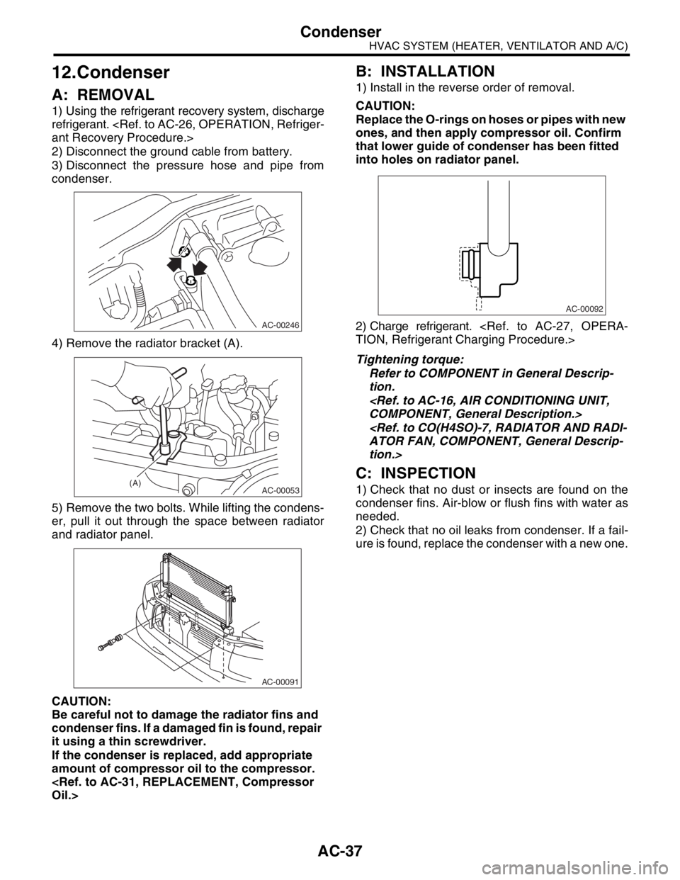
3) Disconnect the pressure hose and pipe from
condenser.
4) Remove the radiator bracket (A).
5) Remove the two bolts. While lifting the condens-
er, pull it out through the space between radiator
and radiator panel.
CAUTION:
Be careful not to damage the radiator fins and
condenser fins. If a damaged fin is found, repair
it using a thin screwdriver.
If the condenser is replaced, add appropriate
amount of compressor oil to the compressor.
B: INSTALLATION
1) Install in the reverse order of removal.
CAUTION:
Replace the O-rings on hoses or pipes with new
ones, and then apply compressor oil. Confirm
that lower guide of condenser has been fitted
into holes on radiator panel.
2) Charge refrigerant.
Tightening torque:
Refer to COMPONENT in General Descrip-
tion.
tion.>
C: INSPECTION
1) Check that no dust or insects are found on the
condenser fins. Air-blow or flush fins with water as
needed.
2) Check that no oil leaks from condenser. If a fail-
ure is found, replace the condenser with a new one.
AC-00246
AC-00053(A)
AC-00091
AC-00092
Page 42 of 2870
AC-40
HVAC SYSTEM (HEATER, VENTILATOR AND A/C)
Evaporator
15.Evaporator
A: REMOVAL
1) Perform the refrigerant recovery operation, and
then disconnect the toe board area A/C pipe.
cedure.>
2) Remove the glove box.
3) Remove blower motor unit assembly.
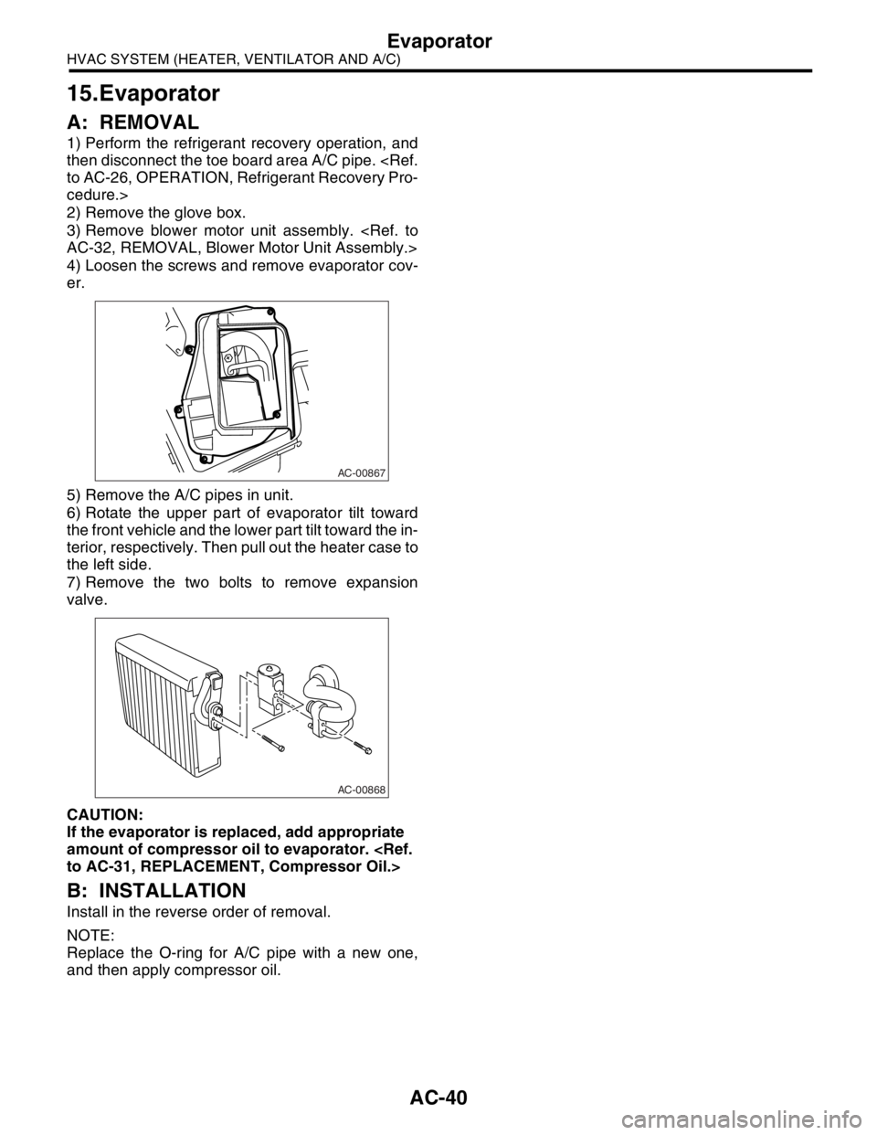
4) Loosen the screws and remove evaporator cov-
er.
5) Remove the A/C pipes in unit.
6) Rotate the upper part of evaporator tilt toward
the front vehicle and the lower part tilt toward the in-
terior, respectively. Then pull out the heater case to
the left side.
7) Remove the two bolts to remove expansion
valve.
CAUTION:
If the evaporator is replaced, add appropriate
amount of compressor oil to evaporator.
B: INSTALLATION
Install in the reverse order of removal.
NOTE:
Replace the O-ring for A/C pipe with a new one,
and then apply compressor oil.
AC-00867
AC-00868
Page 43 of 2870
AC-41
HVAC SYSTEM (HEATER, VENTILATOR AND A/C)
Hose and Tube
16.Hose and Tube
A: REMOVAL
CAUTION:
When disconnecting/connecting hoses, do not
apply excessive force to them. Confirm that no
torsion and excessive tension exists after install-
ing.
Seal the disconnected hose with a plug or vi-
nyl tape to prevent foreign matters from enter-
ing.
1) Disconnect the ground cable from battery.
2) Using the refrigerant recovery system, dis-
charge refrigerant.
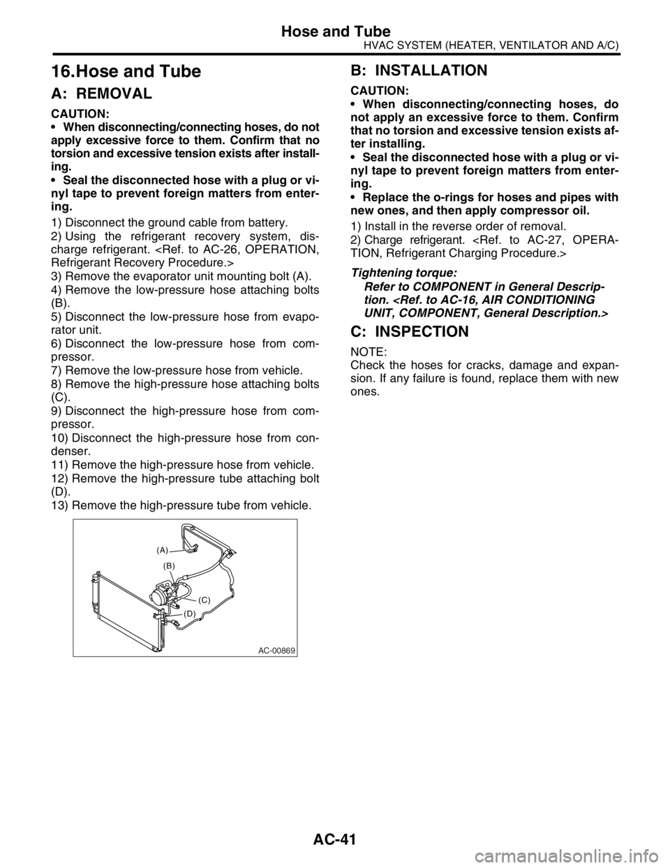
3) Remove the evaporator unit mounting bolt (A).
4) Remove the low-pressure hose attaching bolts
(B).
5) Disconnect the low-pressure hose from evapo-
rator unit.
6) Disconnect the low-pressure hose from com-
pressor.
7) Remove the low-pressure hose from vehicle.
8) Remove the high-pressure hose attaching bolts
(C).
9) Disconnect the high-pressure hose from com-
pressor.
10) Disconnect the high-pressure hose from con-
denser.
11) Remove the high-pressure hose from vehicle.
12) Remove the high-pressure tube attaching bolt
(D).
13) Remove the high-pressure tube from vehicle.
B: INSTALLATION
CAUTION:
When disconnecting/connecting hoses, do
not apply an excessive force to them. Confirm
that no torsion and excessive tension exists af-
ter installing.
Seal the disconnected hose with a plug or vi-
nyl tape to prevent foreign matters from enter-
ing.
Replace the o-rings for hoses and pipes with
new ones, and then apply compressor oil.
1) Install in the reverse order of removal.
2) Charge refrigerant.
Tightening torque:
Refer to COMPONENT in General Descrip-
tion.
C: INSPECTION
NOTE:
Check the hoses for cracks, damage and expan-
sion. If any failure is found, replace them with new
ones.
AC-00869
(A)
(C) (B)
(D)
Page 104 of 2870

AB-4
AIRBAG SYSTEM
General Description
Do not drop the airbag modulator parts, subject
them to high temperature over 93°C (199°F), or let
water, oil, or grease get on them; otherwise, the in-
ternal parts may be damaged and reliability greatly
lowered.
If any damage, opening, or rust is found on the
airbag system wire harness, do not attempt to re-
pair using soldering equipment. Be sure to replace
the faulty harness with a new genuine part.
Install the wire harness securely with the speci-
fied clips to avoid interference or tangled up with
other parts. Do not allow water or oil to come in contact with
the connector terminals. Do not touch the connec-
tor terminals.
Either of the airbag modules for driver, passen-
ger or side, or pretensioner must not be disassem-
bled.
The removed front seat with the airbag module
must be kept at least 200 mm (8 in) away from walls
and other objects.
Do not use the airbag or pretensioner parts from
other vehicles. Always replace defective parts with
new ones.
Never reuse a deployed airbag or pretensioner.
When painting or performing sheet metal work
on the front part of the vehicle, including the front
wheel apron, front fender, and front side frame, re-
move the front sub sensors and wire harness of the
airbag system.
AB-00123
AB-00124
AB-00125
(1) More than 200 mm (8 in)
AB-00126
AB-00779
AB-00128
(1)
Page 112 of 2870

AB-12
AIRBAG SYSTEM
Inspection Locations After a Collision
3. Inspection Locations After a
Collision
A: REPLACEMENT
When airbag system is deployed, replace the fol-
lowing parts.
1. FRONT COLLISION
1) Driver’s airbag module
2) Passenger’s airbag module
3) Driver’s seat belt (pretensioner, lap seat belt pre-
tensioner)
4) Passenger’s seat belt (pretensioner)
5) Airbag control module
6) Front sub-sensor
7) Roll connector
2. SIDE COLLISION
1) Airbag control module
2) Side airbag module (operating side seat bag)
3) Side airbag sensor (operating side)
3. INSPECTION OF OTHER PARTS
Check for the following parts, replace the damaged
parts with new ones.
1) Steering wheel and steering shaft
Check the steering wheel and steering shaft for
mounting condition and deflection of axial and radi-
al direction. Check the steering shaft for deflection
of axial direction with tilt lever released. (After a col-
lision, absorbing part of steering shaft may inflate.)
2) Check the direct type connector of driver’s air-
bag module, pretensioner, etc. for damage, and
also check each harness for pinch and connector
damage. If damage is found, replace the harness
as a unit.
B: INSPECTION
If the vehicle is involved in a collision on any side,
even if it is a slight collision, be sure to check the
following system parts.
1. DRIVER’S AIRBAG MODULE
1) Check for the following, and replace damaged
parts with new ones.
Airbag module is cracked or deformed.
Harness and/or connector is cracked, deformed
or open. Lead wire is exposed.
The module surface is fouled with grease, oil,
water or cleaning solvent.
2) When installing a new driver’s airbag module,
check the following. If necessary, install a new air-
bag module and steering wheel.
The steering wheel is in the way, making it diffi-
cult to install the airbag module. The clearance between the driver’s airbag mod-
ule and steering wheel is not constant.
The steering wheel deformation in axial and radi-
al directions exceed limits.
Specifications:
Height deflection A
Less than 6 mm (0.24 in)
O.D. deflection L
Less than 17 mm (0.67 in)
2. PASSENGER’S AIRBAG MODULE
Check for the following, and replace damaged
parts with new ones.
Airbag module is cracked or deformed.
Harness and/or connector is cracked, deformed
or open. Lead wire is exposed.
Mounting bracket is cracked or deformed.
3. SIDE AIRBAG MODULE
Check for the following, and replace damaged
parts with new ones.
Front seat is damaged or deformed.
Harness and/or connector is cracked, deformed
or open.
Lead wire is exposed.
4. AIRBAG CONTROL MODULE
Check for the following, and replace damaged
parts with new ones.
Control module is cracked or deformed.
Mounting bracket is cracked or deformed.
Connector is scratched or deformed.
Airbag is deployed.
Side airbag is deployed.
AB-00028
L
A
Page 136 of 2870

AB-4
AIRBAG SYSTEM (DIAGNOSTIC)
General Description
3. General Description
A: CAUTION
When servicing a vehicle, be sure to turn the ig-
nition switch to OFF, disconnect the ground cable
from battery, and wait for more than 20 seconds
before starting work.
The airbag system is fitted with a backup power
source. If the airbag system is serviced within 20
seconds after the ground cable is disconnected, it
may inflate.
If sensors, airbag module, airbag control module,
pretensioner, and harness are deformed or dam-
aged, replace them with new genuine parts.
Do not use the airbag system and pretensioners
on other vehicles. When replacing parts, be sure to
replace them with new parts.
When checking the system, be sure to use a dig-
ital circuit tester. Use of an analog circuit tester may
cause the airbag to activate erroneously. When checking, use a test harness. Do not di-
rectly apply the tester probe to any connector termi-
nal of the airbag.
Do not drop the airbag modulator parts, subject
them to high temperature over 93°C (199°F), or let
water, oil, or grease get on them; otherwise, the in-
ternal parts may be damaged and reliability greatly
lowered.
AB-00002
AB-00120
AB-00121
(1) Test harness
AB-00122
(1)
AB-00123
Page 137 of 2870

AB-5
AIRBAG SYSTEM (DIAGNOSTIC)
General Description
If any damage, opening, or rust is found on the
airbag system wiring harness, do not attempt to re-
pair using soldering equipment. Be sure to replace
the faulty harness with a new genuine part.
Install the wiring harness securely with the spec-
ified clips to avoid interference or tangled up with
other parts.
Do not allow water or oil to come in contact with
the connector terminals. Do not touch the connec-
tor terminals. Either of the airbag modules for driver, passen-
ger or side, or pretensioner must not be disassem-
bled.
The airbag module cannot be used again once
inflated.
After removal, keep the airbag module with the
pad facing upward on a dry, clean, and flat surface
away from heat and light sources, and moisture
and dust.
Do not check continuity of either of the airbag
modules for driver, passenger or side, or preten-
sioner.
AB-00124
AB-00125
AB-00126
AB-00127
AB-00056
AB-00006