Page 782 of 1833
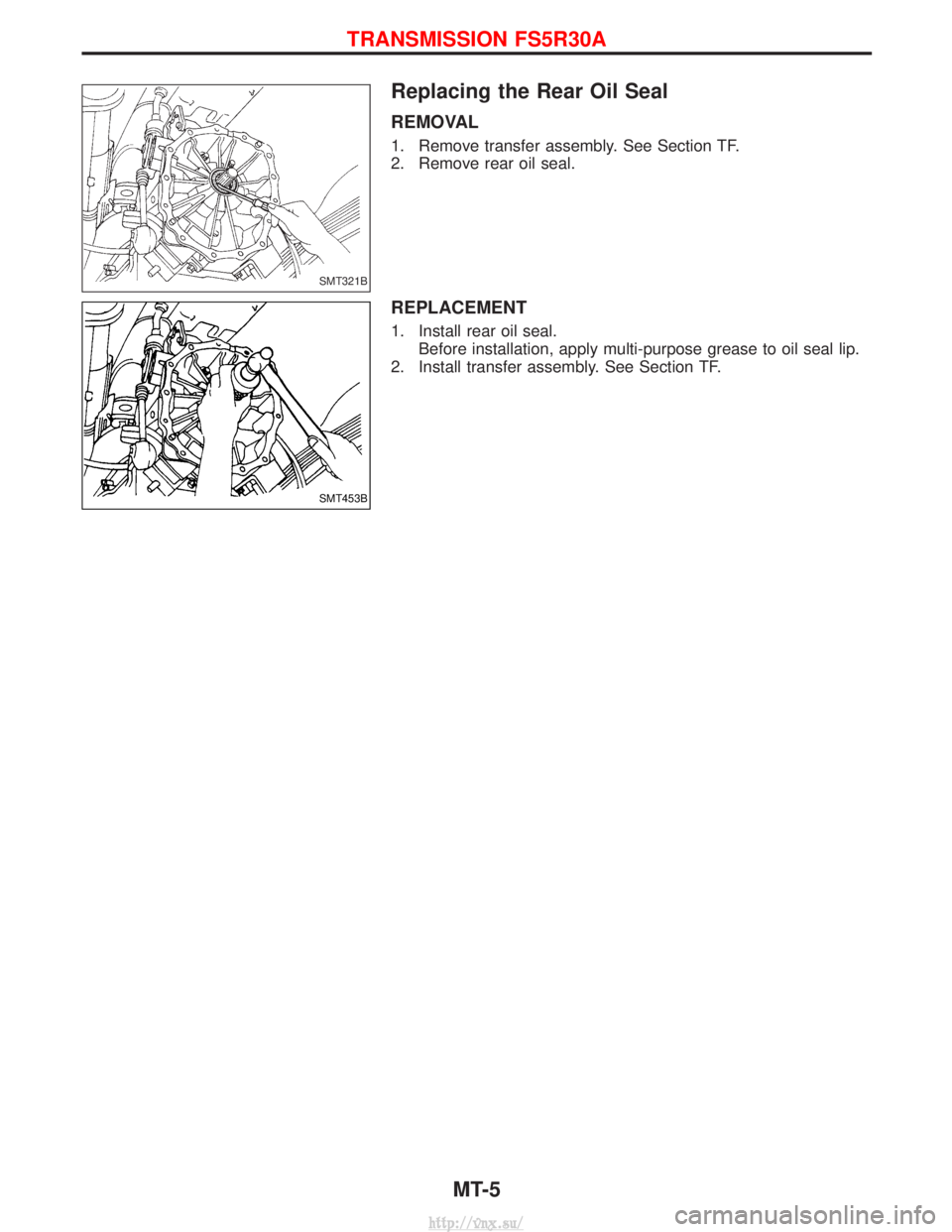
Replacing the Rear Oil Seal
REMOVAL
1. Remove transfer assembly. See Section TF.
2. Remove rear oil seal.
REPLACEMENT
1. Install rear oil seal.Before installation, apply multi-purpose grease to oil seal lip.
2. Install transfer assembly. See Section TF.
SMT321B
SMT453B
TRANSMISSION FS5R30A
MT-5
http://vnx.su/
Page 783 of 1833
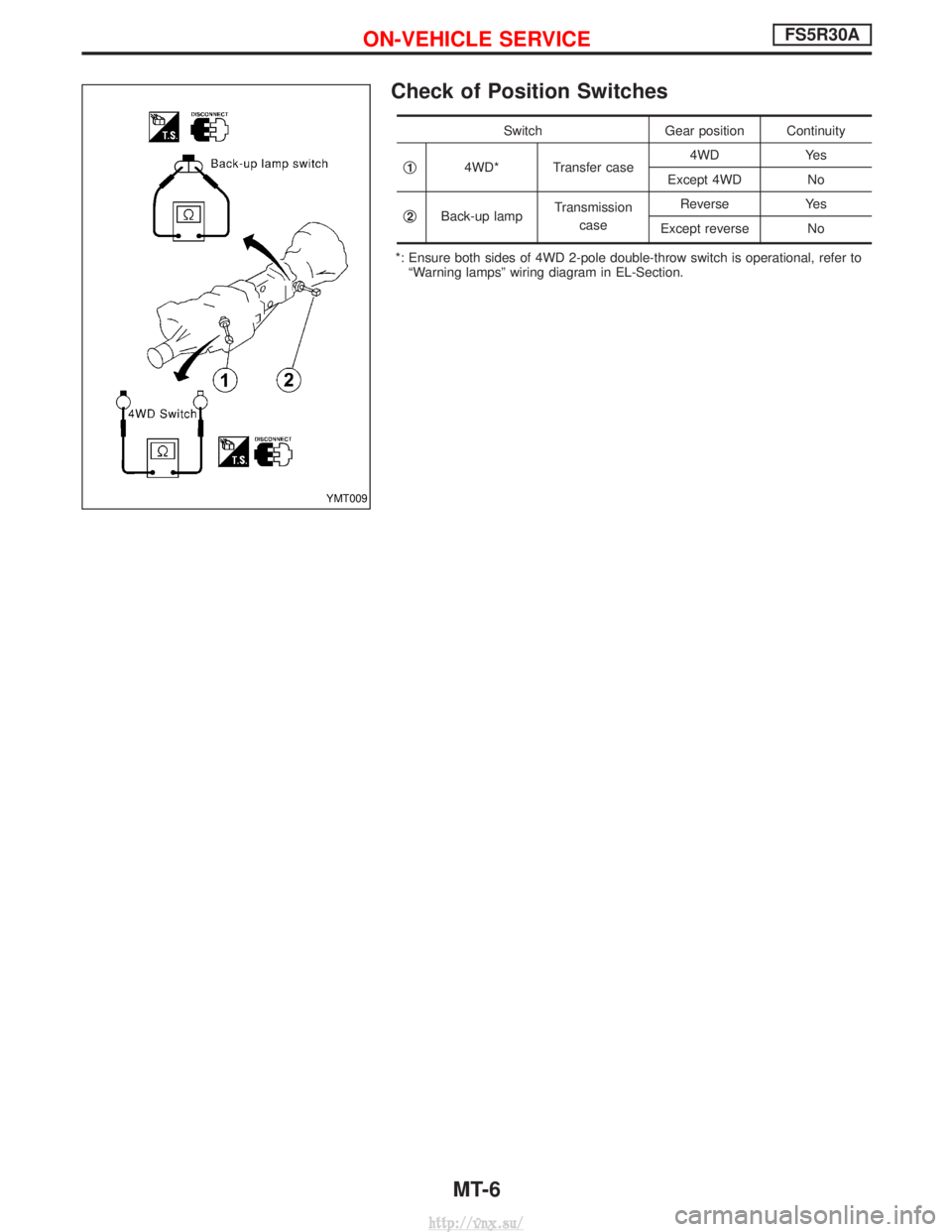
Check of Position Switches
SwitchGear position Continuity
q
14WD* Transfer case 4WD Yes
Except 4WD No
q
2Back-up lamp Transmission
case Reverse Yes
Except reverse No
*: Ensure both sides of 4WD 2-pole double-throw switch is operational, refer to ªWarning lampsº wiring diagram in EL-Section.
YMT009
ON-VEHICLE SERVICEFS5R30A
MT-6
http://vnx.su/
Page 784 of 1833
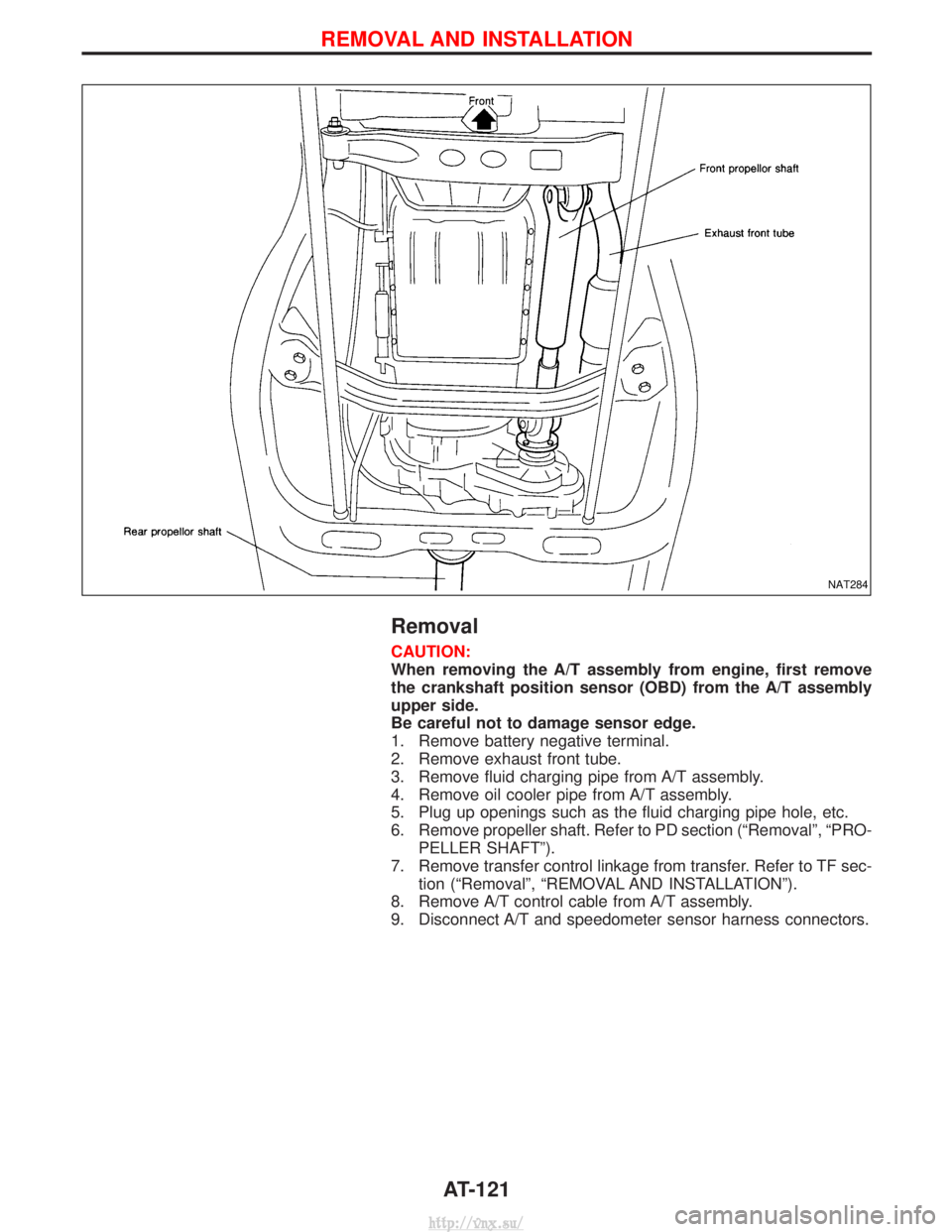
Removal
Transmission has to be removed as a unit together with transfer
box.
Remove transmission assembly as follows:
IDisconnect negative battery terminal.
I Remove shift levers of transmission and transfer.
I Remove front and rear propeller shafts. Ð Refer to PD section.
I Insert plug into rear oil seal after removing propeller shaft.
I Remove RPM-sensor from transmission upper side.
CAUTION:
Be careful not to damage spline, sleeve yoke and rear oil seal,
when removing propeller shaft.
I Remove torsion bar spring. Ð Refer to FA Section.
I Remove third crossmember (the one supporting front differen-
tial).
I Remove fifth crossmember (the one situated at the rear of
transfer).
I Support transmission and transfer with a suitable transmission
jack.
WARNING:
Support transmission and transfer with suitable jacks, while
removing them.
I Remove fourth crossmember (the one supporting transmis-
sion).
I Remove clutch operating cylinder.
I Remove starter motor.
I Remove exhaust tube bracket from transmission.
I Disconnect electrical connectors.
I Remove transmission from engine.
REMOVAL AND INSTALLATIONFS5R30A
MT-7
http://vnx.su/
Page 785 of 1833
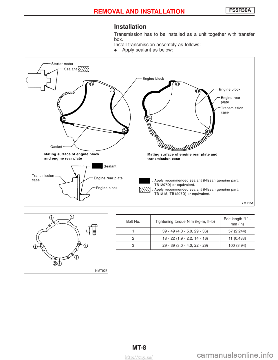
Installation
Transmission has to be installed as a unit together with transfer
box.
Install transmission assembly as follows:
IApply sealant as below:
Bolt No. Tightening torque N×m (kg-m, ft-lb) Bolt length ªLº -
mm (in)
1 39 - 49 (4.0 - 5.0, 29 - 36) 57 (2.244)
2 18 - 22 (1.9 - 2.2, 14 - 16) 11 (0.433)
3 29 - 39 (3.0 - 4.0, 22 - 29) 100 (3.94)
YMT151
NMT027
REMOVAL AND INSTALLATIONFS5R30A
MT-8
http://vnx.su/
Page 786 of 1833
IRaise the unit with a hoist.
I Position the transmission assembly on a portable jack and
secure it with a suitable tool.
Lift the assembly until the gearbox input shaft faces its hous-
ing.
Move the assembly towards the engine. The assembly must be
rotated slightly so that the starter motor housing clears the
projection on the companion floor. Insert input shaft into its
housing (slightly raising the rear of the transfer box may facili-
tate the introduction of the shaft into its housing).
I Tighten the screws securing the gearbox to the engine.
:39-49N ×m (4.0 - 5.0 kg-m, 29 - 36 ft-lb)
I Connect the electrical wiring. Secure with the respective clips.
I Fit the RPM-sensor to the transmission upper side.
I Fit the exhaust pipe support bracket to the transfer box.
:13-16N ×m (1.3 - 1.6 kg-m ,9-12ft-lb)
I Fit the starter motor. Secure the earth wire to the starter motor
lower screw.
:31-41N ×m (3.2 - 4.2 kg-m, 23 - 30 ft-lb)
I Fit the clutch slave cylinder.
:30-40N ×m (3.1 - 4.1 kg-m, 22 - 30 ft-lb)
I Install fourth crossmember (Note the ªfrontº mark).
Crossmember fixing bolts to chassis:
:41-52N ×m (4.2 - 5.3 kg-m, 30 - 38 ft-lb)
Crossmember fixing bolts to transmission:
:68-87N ×m (6.9 - 8.9 kg-m, 50 - 64 ft-lb)
I Take away the portable jack holding boxes assembly.
I Install fifth crossmember.
:59-78N ×m (6.0 - 8.0 kg-m, 43 - 58 ft-lb)
I Install third crossmember.
: Screws: 41 - 52 N ×m (4.2 - 5.3 kg-m,
30 - 38 ft-lb)
Nuts: 68 - 87 N ×m (6.9 - 8.9 kg-m,
50 - 64 ft-lb)
I Install torsion bar springs. Ð Refer to FA section.
I Install front and rear propeller shafts. Ð Refer to PD section.
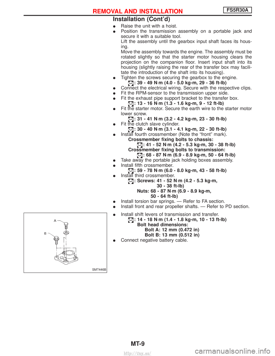
I Install shift levers of transmission and transfer.
:14-18N ×m (1.4 - 1.8 kg-m, 10 - 13 ft-lb)
Bolt head dimensions: Bolt A: 12 mm (0.472 in)
Bolt B: 13 mm (0.512 in)
I Connect negative battery cable.
SMT446B
REMOVAL AND INSTALLATIONFS5R30A
Installation (Cont'd)
MT-9
http://vnx.su/
Page 932 of 1833
Revolution Sensor Replacement
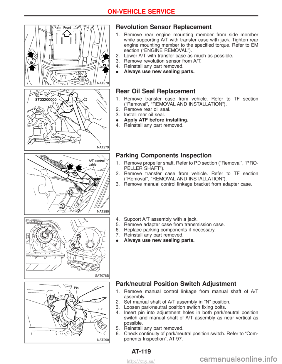
1. Remove rear engine mounting member from side memberwhile supporting A/T with transfer case with jack. Tighten rear
engine mounting member to the specified torque. Refer to EM
section (ªENGINE REMOVALº).
2. Lower A/T with transfer case as much as possible.
3. Remove revolution sensor from A/T.
4. Reinstall any part removed.
I Always use new sealing parts.
Rear Oil Seal Replacement
1. Remove transfer case from vehicle. Refer to TF section
(ªRemovalº, ªREMOVAL AND INSTALLATIONº).
2. Remove rear oil seal.
3. Install rear oil seal.
I Apply ATF before installing.
4. Reinstall any part removed.
Parking Components Inspection
1. Remove propeller shaft. Refer to PD section (ªRemovalº, ªPRO- PELLER SHAFTº).
2. Remove transfer case from vehicle. Refer to TF section (ªRemovalº, ªREMOVAL AND INSTALLATIONº).
3. Remove manual control linkage bracket from adapter case.
4. Support A/T assembly with a jack.
5. Remove adapter case from transmission case.
6. Replace parking components if necessary.
7. Reinstall any part removed.
I Always use new sealing parts.
Park/neutral Position Switch Adjustment
1. Remove manual control linkage from manual shaft of A/T
assembly.
2. Set manual shaft of A/T assembly in ªNº position.
3. Loosen park/neutral position switch fixing bolts.
4. Insert pin into adjustment holes in both park/neutral position switch and manual shaft of A/T assembly as near vertical as
possible.
5. Reinstall any part removed.
6. Check continuity of park/neutral position switch. Refer to ªCom- ponents Inspectionº, AT-97.
NAT278
NAT279
NAT280
SAT078B
NAT290
ON-VEHICLE SERVICE
AT-119
http://vnx.su/
Page 934 of 1833
Removal
CAUTION:
When removing the A/T assembly from engine, first remove
the crankshaft position sensor (OBD) from the A/T assembly
upper side.
Be careful not to damage sensor edge.
1. Remove battery negative terminal.
2. Remove exhaust front tube.
3. Remove fluid charging pipe from A/T assembly.
4. Remove oil cooler pipe from A/T assembly.
5. Plug up openings such as the fluid charging pipe hole, etc.
6. Remove propeller shaft. Refer to PD section (ªRemovalº, ªPRO-PELLER SHAFTº).
7. Remove transfer control linkage from transfer. Refer to TF sec- tion (ªRemovalº, ªREMOVAL AND INSTALLATIONº).
8. Remove A/T control cable from A/T assembly.
9. Disconnect A/T and speedometer sensor harness connectors.
NAT284
REMOVAL AND INSTALLATION
AT-121
http://vnx.su/
Page 935 of 1833
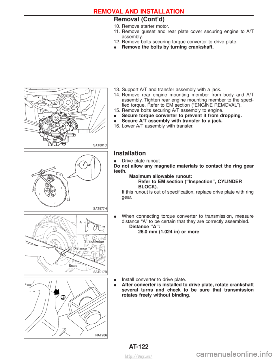
10. Remove starter motor.
11. Remove gusset and rear plate cover securing engine to A/Tassembly.
12. Remove bolts securing torque converter to drive plate.
I Remove the bolts by turning crankshaft.
13. Support A/T and transfer assembly with a jack.
14. Remove rear engine mounting member from body and A/T assembly. Tighten rear engine mounting member to the speci-
fied torque. Refer to EM section (ªENGINE REMOVALº).
15. Remove bolts securing A/T assembly to engine.
I Secure torque converter to prevent it from dropping.
I Secure A/T assembly with transfer to a jack.
16. Lower A/T assembly with transfer.
Installation
I Drive plate runout
Do not allow any magnetic materials to contact the ring gear
teeth. Maximum allowable runout:Refer to EM section (ªInspectionº, CYLINDER
BLOCK).
If this runout is out of specification, replace drive plate with ring
gear.
I When connecting torque converter to transmission, measure
distance ªAº to be certain that they are correctly assembled.
Distance ªAº: 26.0 mm (1.024 in) or more
I Install converter to drive plate.
I After converter is installed to drive plate, rotate crankshaft
several turns and check to be sure that transmission
rotates freely without binding.
SAT801C
SAT977H
SAT017B
NAT286
REMOVAL AND INSTALLATION
Removal (Cont'd)
AT-122
http://vnx.su/