2004 NISSAN TERRANO checking oil
[x] Cancel search: checking oilPage 1398 of 1833
HEATER & AIR CONDITIONERSECTION
HA
CONTENTS
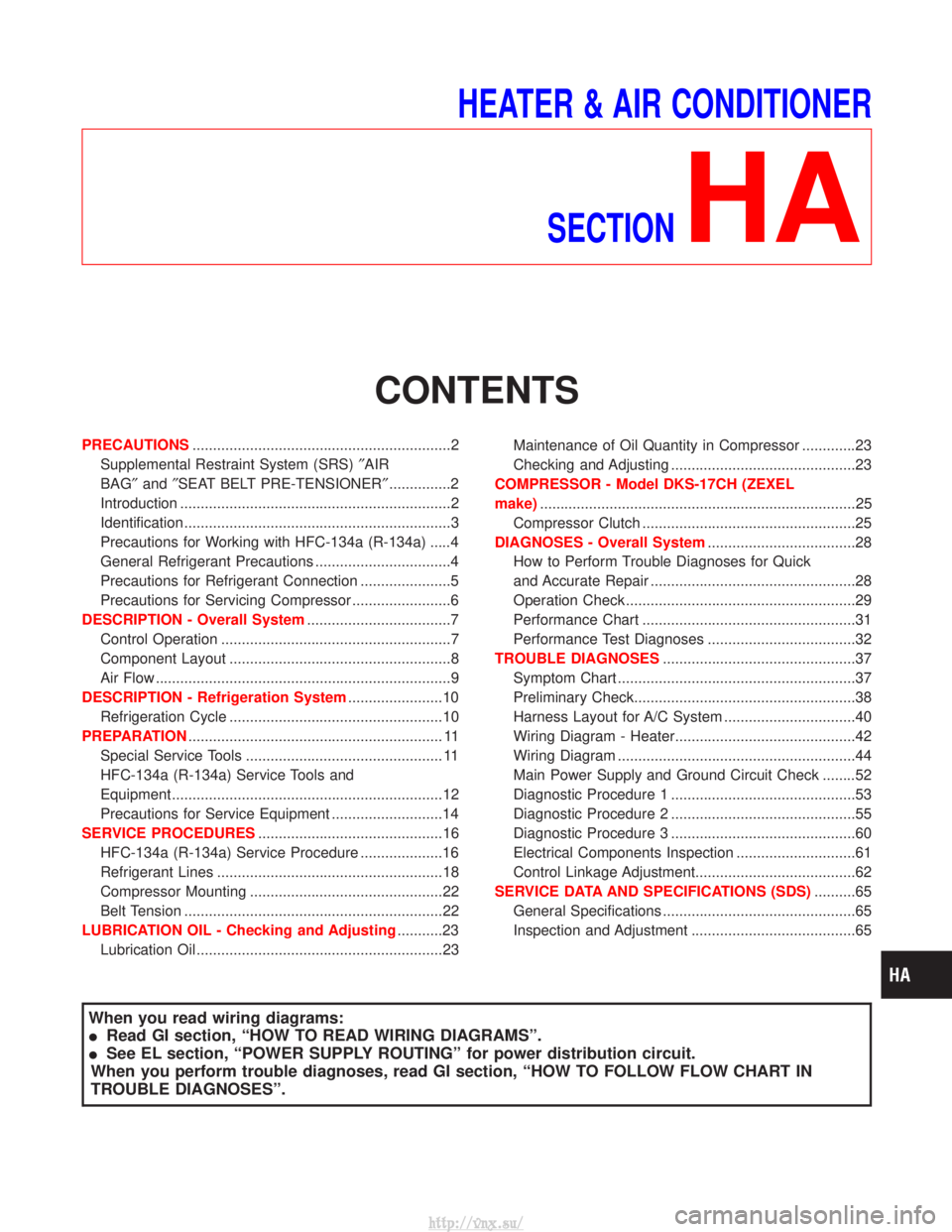
PRECAUTIONS ...............................................................2
Supplemental Restraint System (SRS) ²AIR
BAG² and²SEAT BELT PRE-TENSIONER² ...............2
Introduction ..................................................................2
Identification .................................................................3
Precautions for Working with HFC-134a (R-134a) .....4
General Refrigerant Precautions .................................4
Precautions for Refrigerant Connection ......................5
Precautions for Servicing Compressor ........................6
DESCRIPTION - Overall System ...................................7
Control Operation ........................................................7
Component Layout ......................................................8
Air Flow ........................................................................\
9
DESCRIPTION - Refrigeration System .......................10
Refrigeration Cycle ....................................................10
PREPARATION .............................................................. 11
Special Service Tools ................................................ 11
HFC-134a (R-134a) Service Tools and
Equipment ..................................................................12
Precautions for Service Equipment ...........................14
SERVICE PROCEDURES .............................................16
HFC-134a (R-134a) Service Procedure ....................16
Refrigerant Lines .......................................................18
Compressor Mounting ...............................................22
Belt Tension ...............................................................22
LUBRICATION OIL - Checking and Adjusting ...........23
Lubrication Oil ............................................................23 Maintenance of Oil Quantity in Compressor .............23
Checking and Adjusting .............................................23
COMPRESSOR - Model DKS-17CH (ZEXEL
make) ........................................................................\
.....25
Compressor Clutch ....................................................25
DIAGNOSES - Overall System ....................................28
How to Perform Trouble Diagnoses for Quick
and Accurate Repair ..................................................28
Operation Check ........................................................29
Performance Chart ....................................................31
Performance Test Diagnoses ....................................32
TROUBLE DIAGNOSES ...............................................37
Symptom Chart ..........................................................37
Preliminary Check......................................................38
Harness Layout for A/C System ................................40
Wiring Diagram - Heater............................................42
Wiring Diagram ..........................................................44
Main Power Supply and Ground Circuit Check ........52
Diagnostic Procedure 1 .............................................53
Diagnostic Procedure 2 .............................................55
Diagnostic Procedure 3 .............................................60
Electrical Components Inspection .............................61
Control Linkage Adjustment.......................................62
SERVICE DATA AND SPECIFICATIONS (SDS) ..........65
General Specifications ...............................................65
Inspection and Adjustment ........................................65
When you read wiring diagrams:
I Read GI section, ªHOW TO READ WIRING DIAGRAMSº.
I See EL section, ªPOWER SUPPLY ROUTINGº for power distribution circuit.
When you perform trouble diagnoses, read GI section, ªHOW TO FOLLOW FLOW CHART IN
TROUBLE DIAGNOSESº.
http://vnx.su/
Page 1414 of 1833
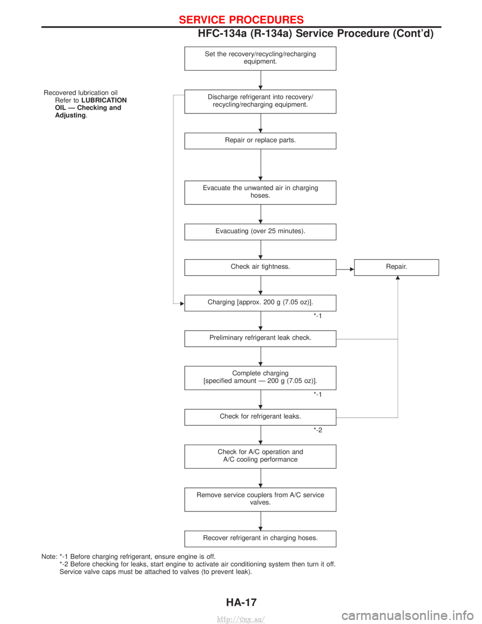
Set the recovery/recycling/rechargingequipment.
Recovered lubrication oilRefer to LUBRICATION
OIL Ð Checking and
Adjusting. Discharge refrigerant into recovery/
recycling/recharging equipment.
Repair or replace parts.
Evacuate the unwanted air in charging hoses.
Evacuating (over 25 minutes).
Check air tightness.ERepair.
G
ECharging [approx. 200 g (7.05 oz)].
*-1
Preliminary refrigerant leak check.
Complete charging
[specified amount Ð 200 g (7.05 oz)].
*-1
Check for refrigerant leaks.
*-2
Check for A/C operation and A/C cooling performance
Remove service couplers from A/C service valves.
Recover refrigerant in charging hoses.
Note: *-1 Before charging refrigerant, ensure engine is off.*-2 Before checking for leaks, start engine to activate air conditioning system then turn it off.
Service valve caps must be attached to valves (to prevent leak).
H
H
H
H
H
H
H
H
H
H
H
H
SERVICE PROCEDURES
HFC-134a (R-134a) Service Procedure (Cont'd)
HA-17
http://vnx.su/
Page 1420 of 1833
Lubrication Oil
Name: Nissan A/C System Oil Type S
Part number: KLH00-PAGS0
Maintenance of Oil Quantity in Compressor
The oil used to lubricate the compressor circulates through the
system with the refrigerant. Whenever any component of the sys-
tem is replaced or a large amount of gas leakage occurs, add oil
to the compressor to maintain the specified amount.
If oil quantity is not maintained properly, the following malfunctions
may result:
ILack of oil: May lead to a seized compressor
I Excessive oil: Inadequate cooling (thermal exchange impeded)
Checking and Adjusting
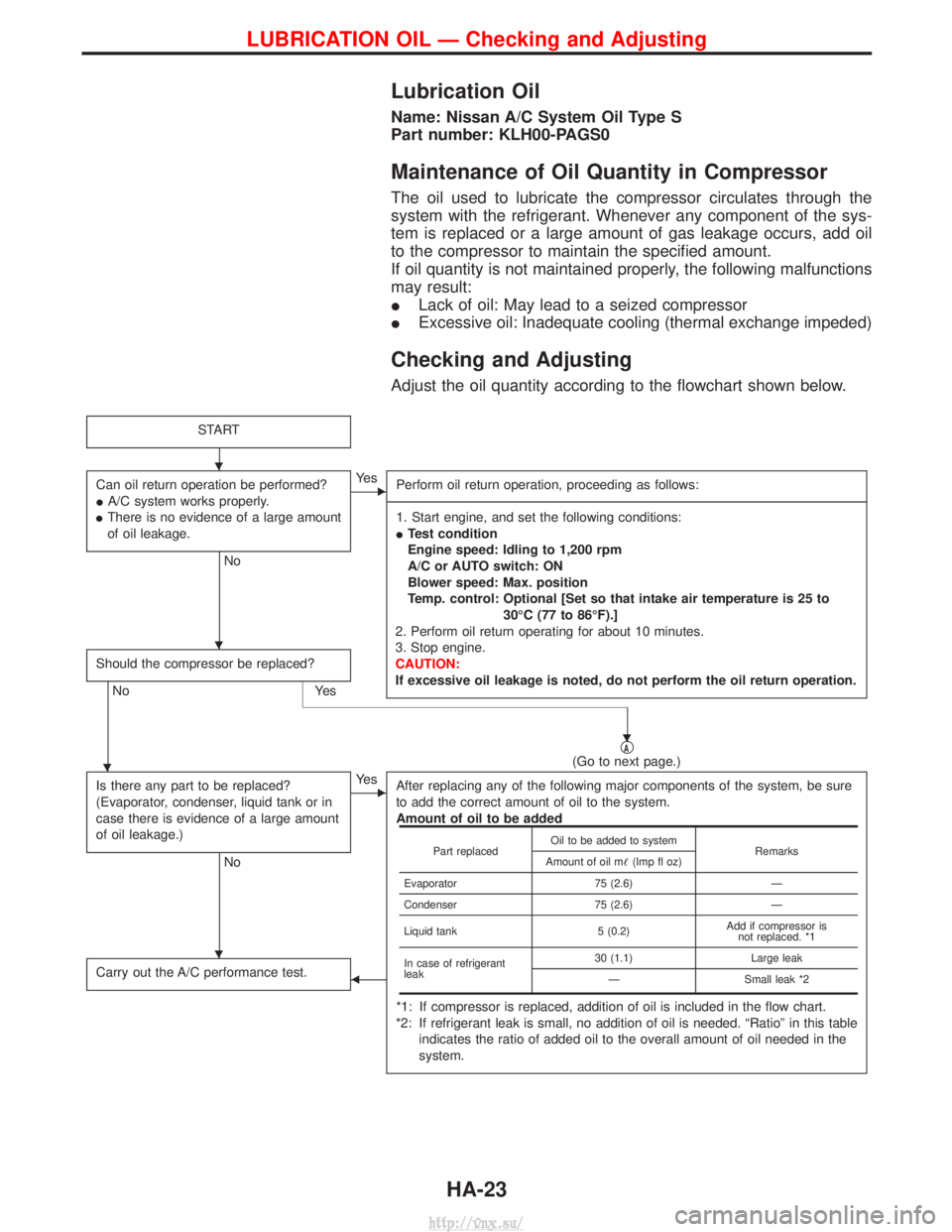
Adjust the oil quantity according to the flowchart shown below.
START
Can oil return operation be performed?
IA/C system works properly.
I There is no evidence of a large amount
of oil leakage.
No
EYe s
Perform oil return operation, proceeding as follows:
------------------------------------------------------------------------------------------------------------------------------------------------------------------------------------------------------------------------------------------------------------------------------------------------------------------------------------------------------------------------------------------------------------------------------------------------------------------------------------------------------------------------------------------------------------- 1. Start engine, and set the following conditions:
I Test condition
Engine speed: Idling to 1,200 rpm
A/C or AUTO switch: ON
Blower speed: Max. position
Temp. control: Optional [Set so that intake air temperature is 25 to
30ÉC (77 to 86ÉF).]
2. Perform oil return operating for about 10 minutes.
3. Stop engine.
CAUTION:
If excessive oil leakage is noted, do not perform the oil return operation.
Should the compressor be replaced?
No Yes
qA(Go to next page.)
Is there any part to be replaced?
(Evaporator, condenser, liquid tank or in
case there is evidence of a large amount
of oil leakage.)
No
EYe s After replacing any of the following major components of the system, be sure
to add the correct amount of oil to the system.
Amount of oil to be added
*1: If compressor is replaced, addition of oil is included in the flow chart.
*2: If refrigerant leak is small, no addition of oil is needed. ªRatioº in this table indicates the ratio of added oil to the overall amount of oil needed in the
system.
Carry out the A/C performance test.F
Part replaced Oil to be added to system
Remarks
Amount of oil m (Imp fl oz)
Evaporator 75 (2.6)Ð
Condenser 75 (2.6)Ð
Liquid tank 5 (0.2)Add if compressor is
not replaced. *1
In case of refrigerant
leak 30 (1.1)
Large leak
Ð Small leak *2
H
H
H
H
H
LUBRICATION OIL Ð Checking and Adjusting
HA-23
http://vnx.su/
Page 1421 of 1833
qA
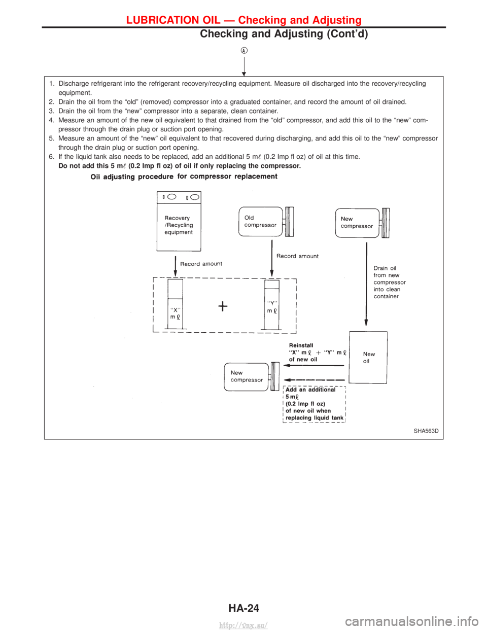
1. Discharge refrigerant into the refrigerant recovery/recycling equipment. Measure oil discharged into the recovery/recyclingequipment.
2. Drain the oil from the ªoldº (removed) compressor into a graduated container, and record the amount of oil drained.
3. Drain the oil from the ªnewº compressor into a separate, clean container.
4. Measure an amount of the new oil equivalent to that drained from the ªoldº compressor, and add this oil to the ªnewº com- pressor through the drain plug or suction port opening.
5. Measure an amount of the ªnewº oil equivalent to that recovered during discharging, and add this oil to the ªnewº compressor through the drain plug or suction port opening.
6. If the liquid tank also needs to be replaced, add an additional 5 m (0.2 Imp fl oz) of oil at this time.
Do not add this 5 m (0.2 Imp fl oz) of oil if only replacing the compressor.
SHA563D
H
LUBRICATION OIL Ð Checking and Adjusting
Checking and Adjusting (Cont'd)
HA-24
http://vnx.su/
Page 1452 of 1833
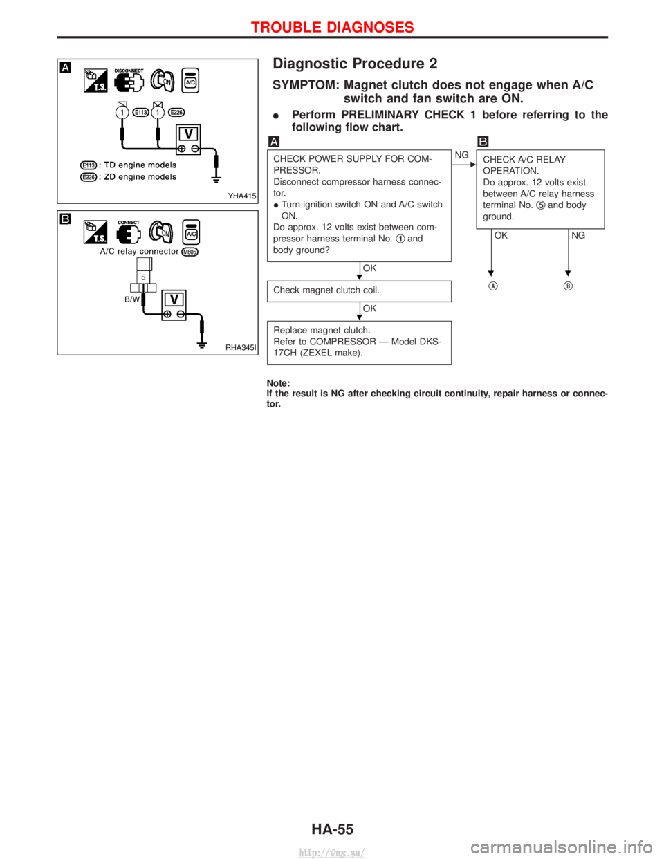
Diagnostic Procedure 2
SYMPTOM: Magnet clutch does not engage when A/Cswitch and fan switch are ON.
IPerform PRELIMINARY CHECK 1 before referring to the
following flow chart.
CHECK POWER SUPPLY FOR COM-
PRESSOR.
Disconnect compressor harness connec-
tor.
ITurn ignition switch ON and A/C switch
ON.
Do approx. 12 volts exist between com-
pressor harness terminal No. q
1and
body ground?
OK
ENG CHECK A/C RELAY
OPERATION.
Do approx. 12 volts exist
between A/C relay harness
terminal No. q
5and body
ground.
OK NG
Check magnet clutch coil.
OK q
AqB
Replace magnet clutch.
Refer to COMPRESSOR Ð Model DKS-
17CH (ZEXEL make).
Note:
If the result is NG after checking circuit continuity, repair harness or connec-
tor.
YHA415
RHA345I
HHH
H
TROUBLE DIAGNOSES
HA-55
http://vnx.su/
Page 1453 of 1833
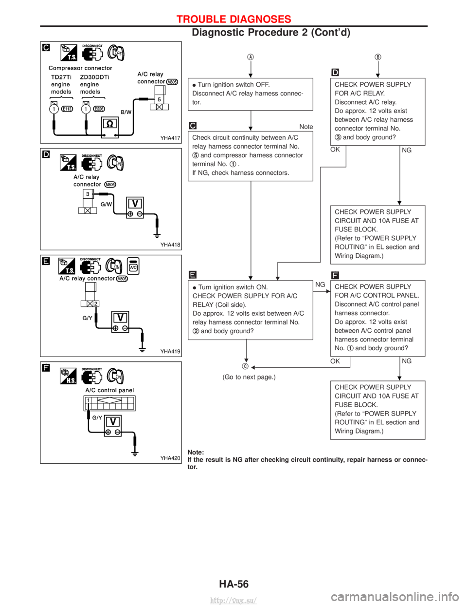
qAqB
ITurn ignition switch OFF.
Disconnect A/C relay harness connec-
tor.CHECK POWER SUPPLY
FOR A/C RELAY.
Disconnect A/C relay.
Do approx. 12 volts exist
between A/C relay harness
connector terminal No.
q
3and body ground?
NG
OK
Note
Check circuit continuity between A/C
relay harness connector terminal No.
q
5and compressor harness connector
terminal No. q
1.
If NG, check harness connectors.
H
CHECK POWER SUPPLY
CIRCUIT AND 10A FUSE AT
FUSE BLOCK.
(Refer to ªPOWER SUPPLY
ROUTINGº in EL section and
Wiring Diagram.)
I Turn ignition switch ON.
CHECK POWER SUPPLY FOR A/C
RELAY (Coil side).
Do approx. 12 volts exist between A/C
relay harness connector terminal No.
q
2and body ground?
H
ENG CHECK POWER SUPPLY
FOR A/C CONTROL PANEL.
Disconnect A/C control panel
harness connector.
Do approx. 12 volts exist
between A/C control panel
harness connector terminal
No.q
1and body ground?
NG
OKFqC
(Go to next page.)
CHECK POWER SUPPLY
CIRCUIT AND 10A FUSE AT
FUSE BLOCK.
(Refer to ªPOWER SUPPLY
ROUTINGº in EL section and
Wiring Diagram.)
Note:
If the result is NG after checking circuit continuity, repair harness or connec-
tor.
YHA417
YHA418
YHA419
YHA420
HH
H
H
H
H
TROUBLE DIAGNOSES
Diagnostic Procedure 2 (Cont'd)
HA-56
http://vnx.su/
Page 1454 of 1833
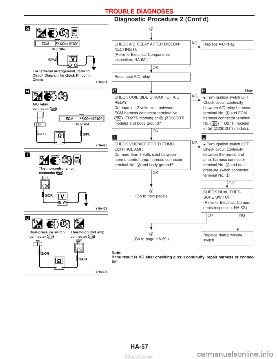
qC
CHECK A/C RELAY AFTER DISCON-
NECTING IT.
(Refer to Electrical Components
Inspection, HA-62.)
OK
ENGReplace A/C relay.
Reconnect A/C relay.
Note
CHECK COIL SIDE CIRCUIT OF A/C
RELAY.
Do approx. 12 volts exist between
ECM harness connector terminal No.
204(TD27Ti models) or q15(ZD30DDTi
models) and body ground?
OK
ENG ITurn ignition switch OFF.
Check circuit continuity
between A/C relay harness
terminal No. q
1and ECM
harness connector terminal
No.
204(TD27Ti models)
or q
15(ZD30DDTi models).
CHECK VOLTAGE FOR THERMO
CONTROL AMP.
Do more than 8 volts exist between
thermo-control amp. harness connector
terminal No. q
2and body ground?
OK
ENG
ITurn ignition switch OFF.
Check circuit continuity
between thermo-control
amp. harness connector
terminal No. q
2and dual-
pressure switch connector
terminal No. q
2.
OK
q
D
(Go to next page.) CHECK DUAL-PRES-
SURE SWITCH.
(Refer to Electrical Compo-
nents Inspection, HA-62.)
NGOK
q
E
(Go to page HA-59.) Replace dual-pressure
switch.
Note:
If the result is NG after checking circuit continuity, repair harness or connec-
tor.
YHA421
YHA422
YHA423
YHA424
H
H
H
H
HH
HH
TROUBLE DIAGNOSES
Diagnostic Procedure 2 (Cont'd)
HA-57
http://vnx.su/
Page 1462 of 1833
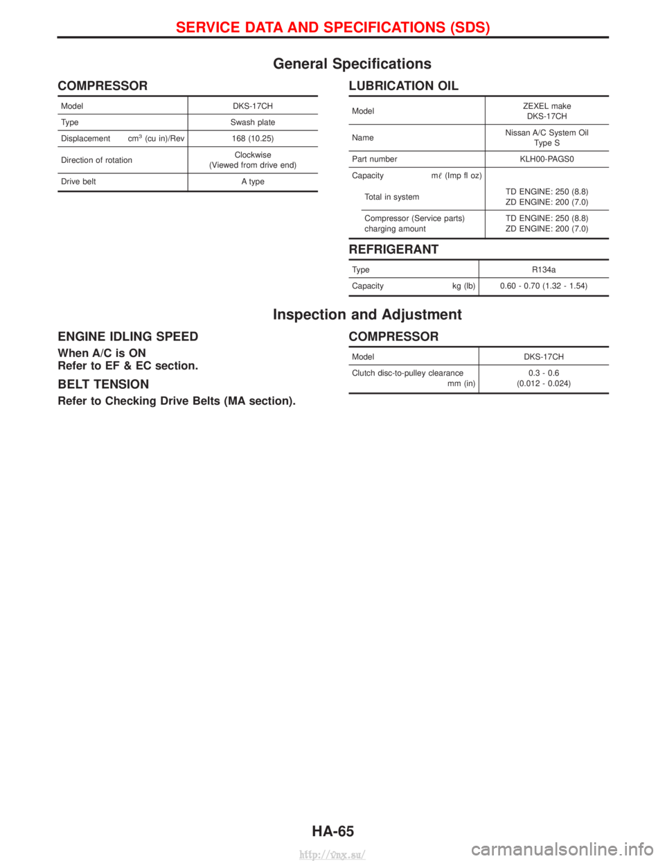
General Specifications
COMPRESSOR
ModelDKS-17CH
Type Swash plate
Displacement cm
3(cu in)/Rev 168 (10.25)
Direction of rotation Clockwise
(Viewed from drive end)
Drive belt A type
LUBRICATION OIL
ModelZEXEL make
DKS-17CH
Name Nissan A/C System Oil
Type S
Part number KLH00-PAGS0
Capacity m (Imp fl oz)
Total in system TD ENGINE: 250 (8.8)
ZD ENGINE: 200 (7.0)
Compressor (Service parts)
charging amount TD ENGINE: 250 (8.8)
ZD ENGINE: 200 (7.0)
REFRIGERANT
Type
R134a
Capacity kg (lb) 0.60 - 0.70 (1.32 - 1.54)
Inspection and Adjustment
ENGINE IDLING SPEED
When A/C is ON
Refer to EF & EC section.
BELT TENSION
Refer to Checking Drive Belts (MA section).
COMPRESSOR
Model DKS-17CH
Clutch disc-to-pulley clearance mm (in)0.3 - 0.6
(0.012 - 0.024)
SERVICE DATA AND SPECIFICATIONS (SDS)
HA-65
http://vnx.su/