2004 NISSAN TERRANO checking oil
[x] Cancel search: checking oilPage 816 of 1833
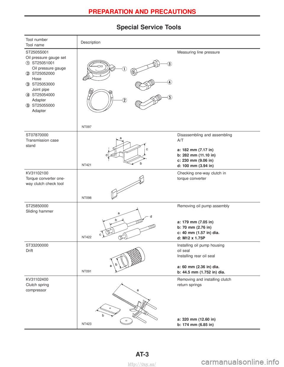
Special Service Tools
Tool number
Tool nameDescription
ST2505S001
Oil pressure gauge set
q
1ST25051001
Oil pressure gauge
q
2ST25052000
Hose
q
3ST25053000
Joint pipe
q
4ST25054000
Adapter
q
5ST25055000
Adapter
NT097
Measuring line pressure
ST07870000
Transmission case
stand
NT421
Disassembling and assembling
A/T
a: 182 mm (7.17 in)
b: 282 mm (11.10 in)
c: 230 mm (9.06 in)
d: 100 mm (3.94 in)
KV31102100
Torque converter one-
way clutch check tool
NT098
Checking one-way clutch in
torque converter
ST25850000
Sliding hammer
NT422
Removing oil pump assembly
a: 179 mm (7.05 in)
b: 70 mm (2.76 in)
c: 40 mm (1.57 in) dia.
d: M12 x 1.75P
ST33200000
Drift
NT091
Installing oil pump housing
oil seal
Installing rear oil seal
a: 60 mm (2.36 in) dia.
b: 44.5 mm (1.752 in) dia.
KV31102400
Clutch spring
compressor
NT423
Removing and installing clutch
return springs
a: 320 mm (12.60 in)
b: 174 mm (6.85 in)
PREPARATION AND PRECAUTIONS
AT- 3
http://vnx.su/
Page 840 of 1833

A/T Fluid Check
FLUID LEAKAGE CHECK
1. Clean area suspected of leaking. Ð for example, mating sur-face of converter housing and transmission case.
2. Start engine, apply foot brake, place selector lever in ªDº posi- tion and wait a few minutes.
3. Stop engine.
4. Check for fresh leakage.
FLUID CONDITION CHECK
Fluid color Suspected cause
Dark or black with burned odor Wear of frictional material
Milky pink Water contamination Ð Road water enter-
ing through filler tube or breather
Varnished fluid, light to dark
brown and tacky Oxidation Ð Over or under filling, Ð Over-
heating
FLUID LEVEL CHECK
Refer to MA section (ªChecking A/T Fluidº, ªCHASSIS AND BODY
MAINTENANCEº).
Stall Test
STALL TEST PROCEDURE
1. Check A/T and engine fluid levels. If necessary, add.
2. Drive vehicle for approx. 10 minutes or until engine oil and ATF
reach operating temperature.ATF operating temperature: 50 - 80ÉC (122 - 176ÉF)
3. Set parking brake and block wheels.
4. Install a tachometer where it can be seen by driver during test.
I It is good practice to put a mark on point of specified
engine rpm on indicator.
5. Start engine, apply foot brake, and place selector lever in ªDº position.
6. Accelerate to wide open throttle gradually while applying foot brake.
7. Quickly note the engine stall revolution and immediately release throttle.
I During test, never hold throttle wide open for more than 5
seconds.
Stall revolution: 2,450 - 2,700 rpm
SAT801A
SAT638A
SAT647B
SAT513G
SAT514G
TROUBLE DIAGNOSIS Ð Basic Inspection
AT-27
http://vnx.su/
Page 1054 of 1833
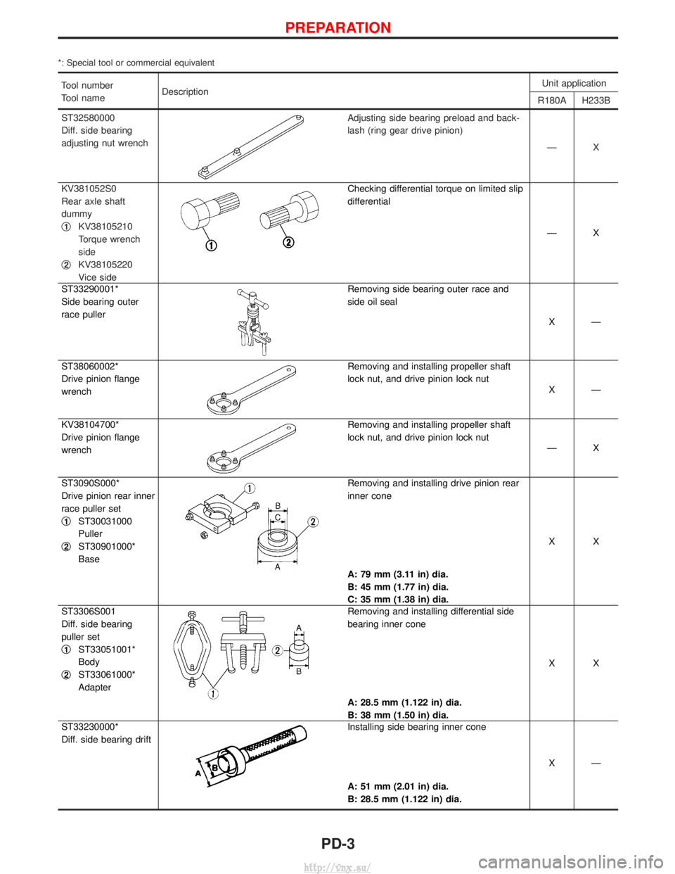
*: Special tool or commercial equivalent
Tool number
Tool nameDescription Unit application
R180A H233B
ST32580000
Diff. side bearing
adjusting nut wrench
Adjusting side bearing preload and back-
lash (ring gear drive pinion) ÐX
KV381052S0
Rear axle shaft
dummy
q
1KV38105210
Torque wrench
side
q
2KV38105220
Vice side
Checking differential torque on limited slip
differential
ÐX
ST33290001*
Side bearing outer
race puller
Removing side bearing outer race and
side oil seal XÐ
ST38060002*
Drive pinion flange
wrench
Removing and installing propeller shaft
lock nut, and drive pinion lock nut XÐ
KV38104700*
Drive pinion flange
wrench
Removing and installing propeller shaft
lock nut, and drive pinion lock nut ÐX
ST3090S000*
Drive pinion rear inner
race puller set
q
1ST30031000
Puller
q
2ST30901000*
Base
Removing and installing drive pinion rear
inner cone
A: 79 mm (3.11 in) dia.
B: 45 mm (1.77 in) dia.
C: 35 mm (1.38 in) dia. XX
ST3306S001
Diff. side bearing
puller set
q
1ST33051001*
Body
q
2ST33061000*
Adapter
Removing and installing differential side
bearing inner cone
A: 28.5 mm (1.122 in) dia.
B: 38 mm (1.50 in) dia. XX
ST33230000*
Diff. side bearing drift
Installing side bearing inner cone
A: 51 mm (2.01 in) dia.
B: 28.5 mm (1.122 in) dia. XÐ
PREPARATION
PD-3
http://vnx.su/
Page 1172 of 1833
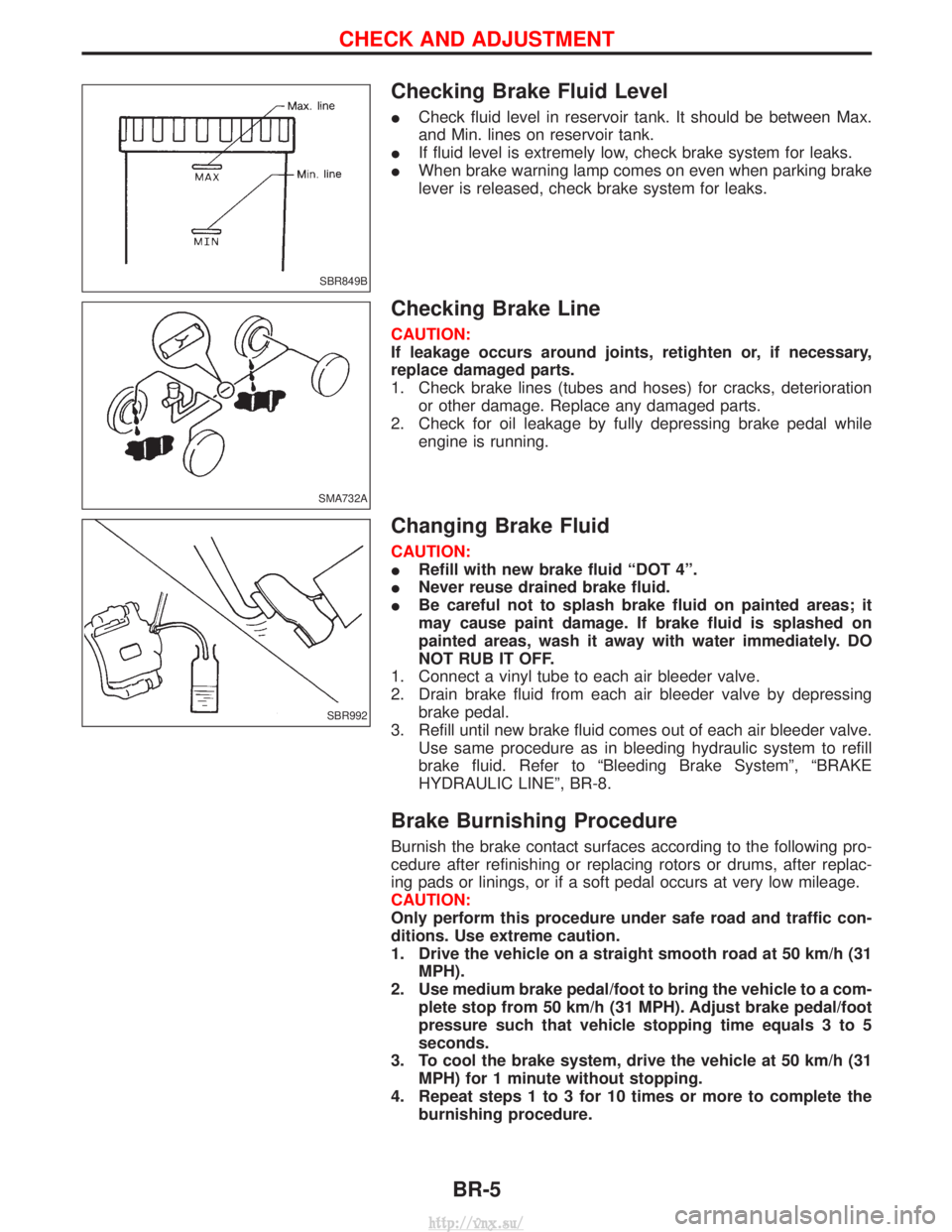
Checking Brake Fluid Level
ICheck fluid level in reservoir tank. It should be between Max.
and Min. lines on reservoir tank.
I If fluid level is extremely low, check brake system for leaks.
I When brake warning lamp comes on even when parking brake
lever is released, check brake system for leaks.
Checking Brake Line
CAUTION:
If leakage occurs around joints, retighten or, if necessary,
replace damaged parts.
1. Check brake lines (tubes and hoses) for cracks, deterioration
or other damage. Replace any damaged parts.
2. Check for oil leakage by fully depressing brake pedal while engine is running.
Changing Brake Fluid
CAUTION:
IRefill with new brake fluid ªDOT 4º.
I Never reuse drained brake fluid.
I Be careful not to splash brake fluid on painted areas; it
may cause paint damage. If brake fluid is splashed on
painted areas, wash it away with water immediately. DO
NOT RUB IT OFF.
1. Connect a vinyl tube to each air bleeder valve.
2. Drain brake fluid from each air bleeder valve by depressing brake pedal.
3. Refill until new brake fluid comes out of each air bleeder valve. Use same procedure as in bleeding hydraulic system to refill
brake fluid. Refer to ªBleeding Brake Systemº, ªBRAKE
HYDRAULIC LINEº, BR-8.
Brake Burnishing Procedure
Burnish the brake contact surfaces according to the following pro-
cedure after refinishing or replacing rotors or drums, after replac-
ing pads or linings, or if a soft pedal occurs at very low mileage.
CAUTION:
Only perform this procedure under safe road and traffic con-
ditions. Use extreme caution.
1. Drive the vehicle on a straight smooth road at 50 km/h (31MPH).
2. Use medium brake pedal/foot to bring the vehicle to a com- plete stop from 50 km/h (31 MPH). Adjust brake pedal/foot
pressure such that vehicle stopping time equals 3 to 5
seconds.
3. To cool the brake system, drive the vehicle at 50 km/h (31 MPH) for 1 minute without stopping.
4. Repeat steps 1 to 3 for 10 times or more to complete the burnishing procedure.
SBR849B
SMA732A
SBR992
CHECK AND ADJUSTMENT
BR-5
http://vnx.su/
Page 1254 of 1833
STEERING SYSTEM
SECTION
ST
CONTENTS
PRECAUTIONS ...............................................................2
Supplemental Restraint System (SRS) ²AIR
BAG² and²SEAT BELT PRE-TENSIONER² ...............2
Precautions for SRS ²AIR BAG² and²SEAT
BELT PRE-TENSIONER² Service ...............................2
Precautions for Steering System .................................2
PREPARATION ................................................................3
Special Service Tools ..................................................3
ON-VEHICLE SERVICE ..................................................4
Checking Steering Wheel Play ....................................4
Checking Neutral Position on Steering Wheel ............4
Front Wheel Turning Angle ..........................................4
Checking and Adjusting Drive Belts ............................4
Checking Fluid Level ...................................................4
Checking Fluid Leakage ..............................................5
Bleeding Hydraulic System..........................................5
Checking Steering Wheel Turning Force ....................6
Checking Hydraulic System.........................................7 STEERING WHEEL AND STEERING COLUMN
............8
Removal and Installation .............................................8
Disassembly and Assembly .......................................10
Inspection................................................................... 11
POWER STEERING GEAR ...........................................12
Description .................................................................12
Removal and Installation ...........................................14
Inspection and Adjustment ........................................15
POWER STEERING OIL PUMP ....................................16
Removal and Installation ...........................................16
STEERING LINKAGE ....................................................17
Removal and Installation ...........................................17
Disassembly and Assembly .......................................19
Inspection...................................................................20
SERVICE DATA AND SPECIFICATIONS (SDS) ..........22
General Specifications ...............................................22
Inspection and Adjustment ........................................22
http://vnx.su/
Page 1258 of 1833
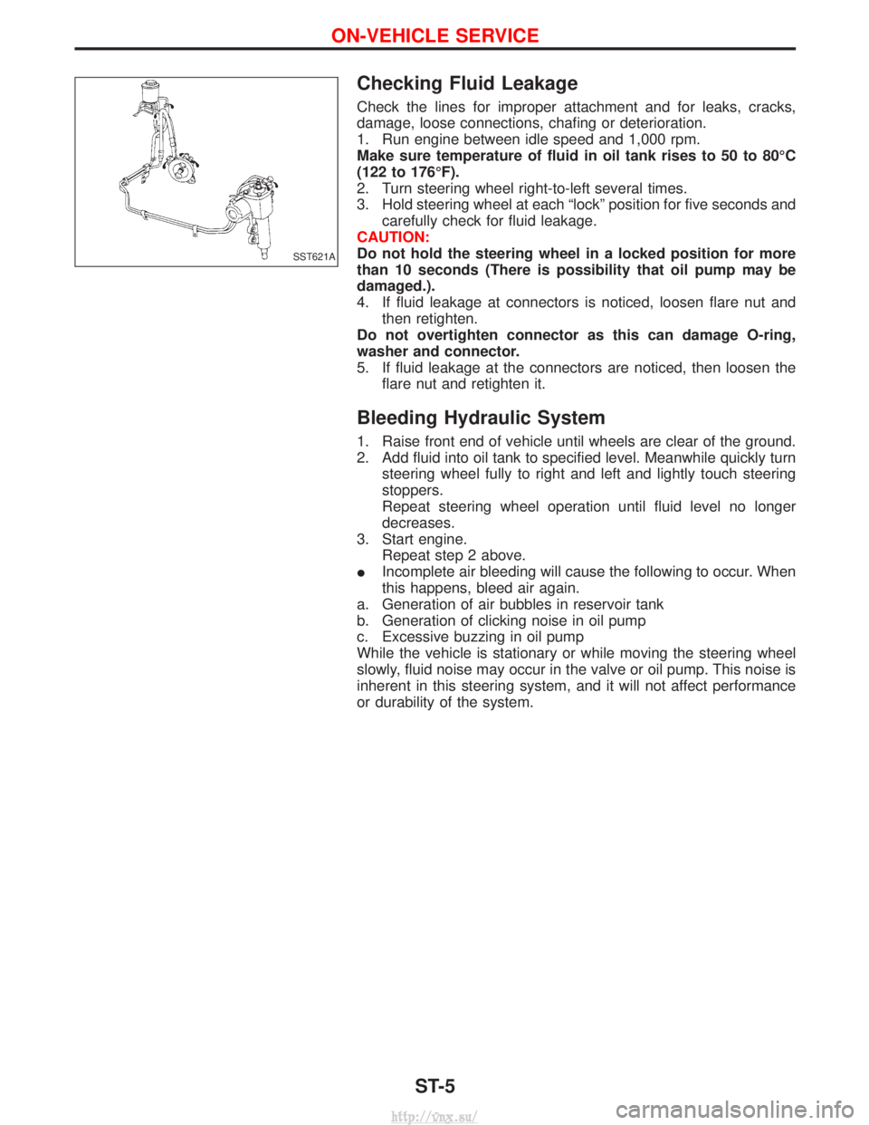
Checking Fluid Leakage
Check the lines for improper attachment and for leaks, cracks,
damage, loose connections, chafing or deterioration.
1. Run engine between idle speed and 1,000 rpm.
Make sure temperature of fluid in oil tank rises to 50 to 80ÉC
(122 to 176ÉF).
2. Turn steering wheel right-to-left several times.
3. Hold steering wheel at each ªlockº position for five seconds andcarefully check for fluid leakage.
CAUTION:
Do not hold the steering wheel in a locked position for more
than 10 seconds (There is possibility that oil pump may be
damaged.).
4. If fluid leakage at connectors is noticed, loosen flare nut and then retighten.
Do not overtighten connector as this can damage O-ring,
washer and connector.
5. If fluid leakage at the connectors are noticed, then loosen the flare nut and retighten it.
Bleeding Hydraulic System
1. Raise front end of vehicle until wheels are clear of the ground.
2. Add fluid into oil tank to specified level. Meanwhile quickly turnsteering wheel fully to right and left and lightly touch steering
stoppers.
Repeat steering wheel operation until fluid level no longer
decreases.
3. Start engine. Repeat step 2 above.
I Incomplete air bleeding will cause the following to occur. When
this happens, bleed air again.
a. Generation of air bubbles in reservoir tank
b. Generation of clicking noise in oil pump
c. Excessive buzzing in oil pump
While the vehicle is stationary or while moving the steering wheel
slowly, fluid noise may occur in the valve or oil pump. This noise is
inherent in this steering system, and it will not affect performance
or durability of the system.
SST621A
ON-VEHICLE SERVICE
ST-5
http://vnx.su/
Page 1259 of 1833
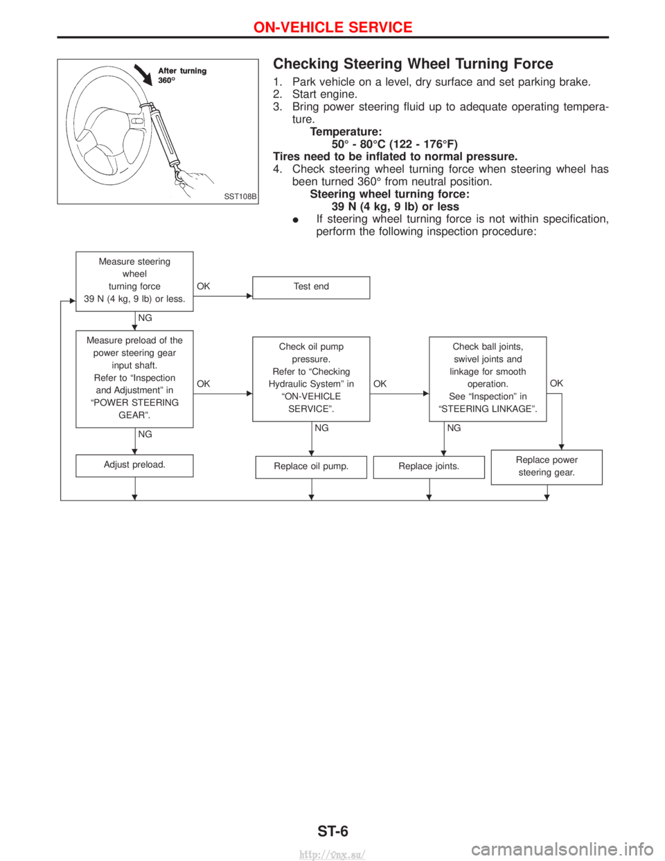
Checking Steering Wheel Turning Force
1. Park vehicle on a level, dry surface and set parking brake.
2. Start engine.
3. Bring power steering fluid up to adequate operating tempera-ture.Temperature: 50É - 80ÉC (122 - 176ÉF)
Tires need to be inflated to normal pressure.
4. Check steering wheel turning force when steering wheel has been turned 360É from neutral position.Steering wheel turning force: 39 N (4 kg, 9 lb) or less
I If steering wheel turning force is not within specification,
perform the following inspection procedure:
E
Measure steering
wheel
turning force
39 N (4 kg, 9 lb) or less.
NG
EOK Test end
Measure preload of the
power steering gear input shaft.
Refer to ªInspection and Adjustmentº in
ªPOWER STEERING GEARº.
NG
EOK Check oil pump
pressure.
Refer to ªChecking
Hydraulic Systemº in ªON-VEHICLESERVICEº.
NG
EOK Check ball joints,
swivel joints and
linkage for smooth operation.
See ªInspectionº in
ªSTEERING LINKAGEº.
NG OK
Adjust preload.Replace oil pump.Replace joints.Replace power
steering gear.
SST108B
H
HHHH
HHHH
ON-VEHICLE SERVICE
ST-6
http://vnx.su/
Page 1260 of 1833
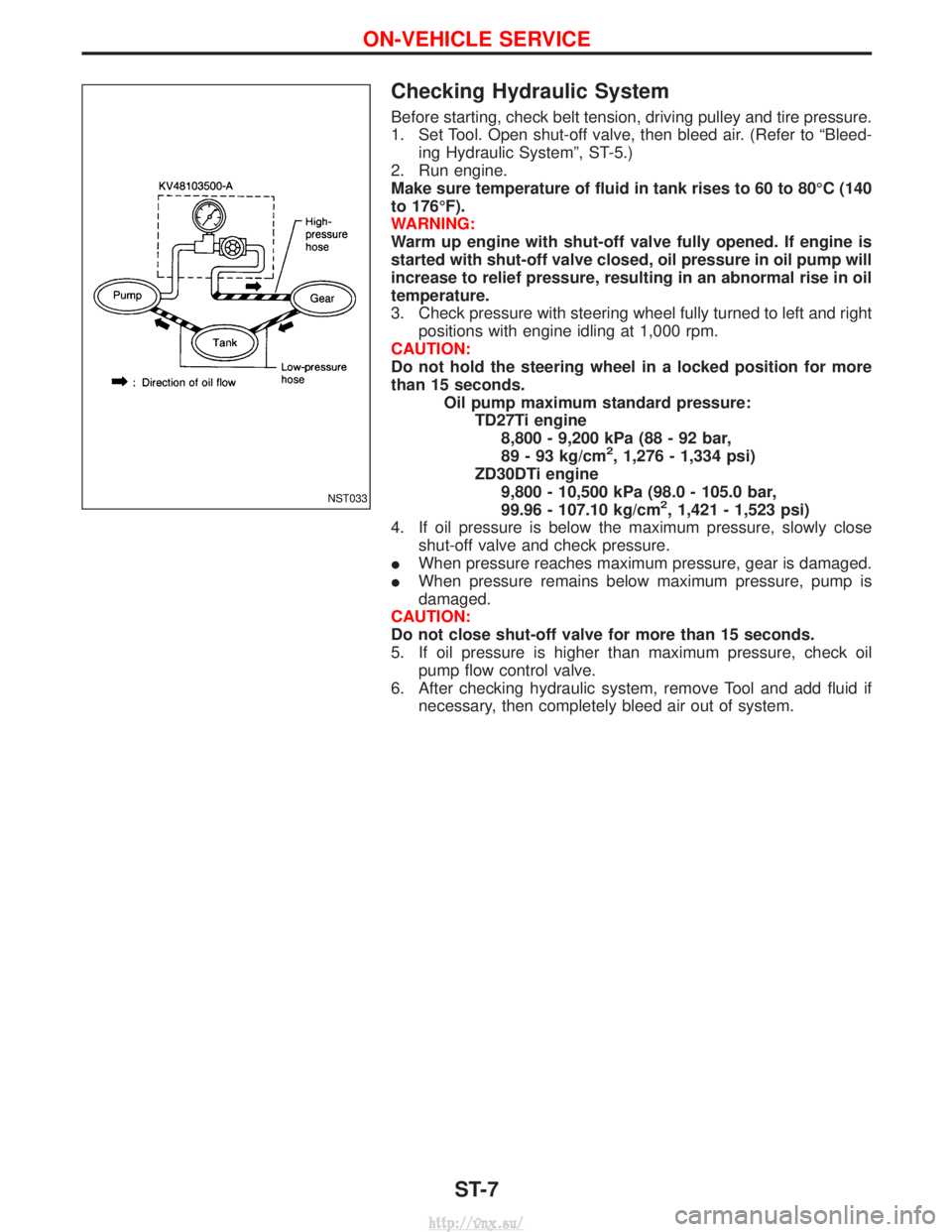
Checking Hydraulic System
Before starting, check belt tension, driving pulley and tire pressure.
1. Set Tool. Open shut-off valve, then bleed air. (Refer to ªBleed-ing Hydraulic Systemº, ST-5.)
2. Run engine.
Make sure temperature of fluid in tank rises to 60 to 80ÉC (140
to 176ÉF).
WARNING:
Warm up engine with shut-off valve fully opened. If engine is
started with shut-off valve closed, oil pressure in oil pump will
increase to relief pressure, resulting in an abnormal rise in oil
temperature.
3. Check pressure with steering wheel fully turned to left and right positions with engine idling at 1,000 rpm.
CAUTION:
Do not hold the steering wheel in a locked position for more
than 15 seconds. Oil pump maximum standard pressure:TD27Ti engine8,800 - 9,200 kPa (88 - 92 bar,
89 - 93 kg/cm
2, 1,276 - 1,334 psi)
ZD30DTi engine 9,800 - 10,500 kPa (98.0 - 105.0 bar,
99.96 - 107.10 kg/cm
2, 1,421 - 1,523 psi)
4. If oil pressure is below the maximum pressure, slowly close shut-off valve and check pressure.
I When pressure reaches maximum pressure, gear is damaged.
I When pressure remains below maximum pressure, pump is
damaged.
CAUTION:
Do not close shut-off valve for more than 15 seconds.
5. If oil pressure is higher than maximum pressure, check oil pump flow control valve.
6. After checking hydraulic system, remove Tool and add fluid if necessary, then completely bleed air out of system.NST033
ON-VEHICLE SERVICE
ST-7
http://vnx.su/