2004 NISSAN TERRANO change time
[x] Cancel search: change timePage 1084 of 1833
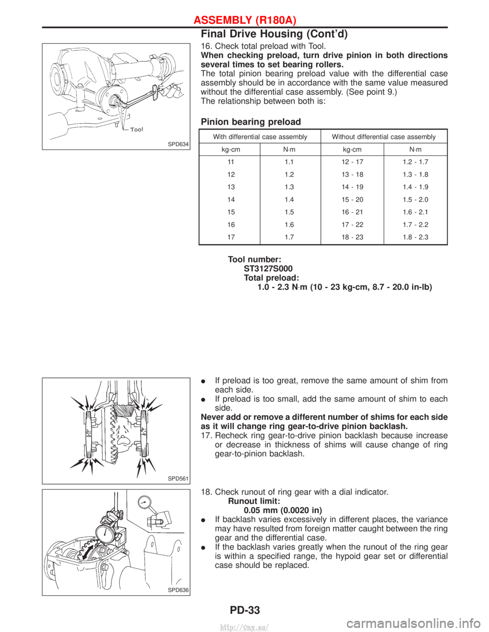
16. Check total preload with Tool.
When checking preload, turn drive pinion in both directions
several times to set bearing rollers.
The total pinion bearing preload value with the differential case
assembly should be in accordance with the same value measured
without the differential case assembly. (See point 9.)
The relationship between both is:
Pinion bearing preload
With differential case assembly Without differential case assemblykg-cm N×m kg-cmN×m
11 1.1 12 - 17 1.2 - 1.7
12 1.2 13 - 18 1.3 - 1.8
13 1.3 14 - 19 1.4 - 1.9
14 1.4 15 - 20 1.5 - 2.0
15 1.5 16 - 21 1.6 - 2.1
16 1.6 17 - 22 1.7 - 2.2
17 1.7 18 - 23 1.8 - 2.3
Tool number: ST3127S000
Total preload:1.0 - 2.3 N ×m (10 - 23 kg-cm, 8.7 - 20.0 in-lb)
I If preload is too great, remove the same amount of shim from
each side.
I If preload is too small, add the same amount of shim to each
side.
Never add or remove a different number of shims for each side
as it will change ring gear-to-drive pinion backlash.
17. Recheck ring gear-to-drive pinion backlash because increase or decrease in thickness of shims will cause change of ring
gear-to-pinion backlash.
18. Check runout of ring gear with a dial indicator. Runout limit:0.05 mm (0.0020 in)
I If backlash varies excessively in different places, the variance
may have resulted from foreign matter caught between the ring
gear and the differential case.
I If the backlash varies greatly when the runout of the ring gear
is within a specified range, the hypoid gear set or differential
case should be replaced.
SPD634
SPD561
SPD636
ASSEMBLY (R180A)
Final Drive Housing (Cont'd)
PD-33
http://vnx.su/
Page 1185 of 1833
Removal and Installation
Inspection
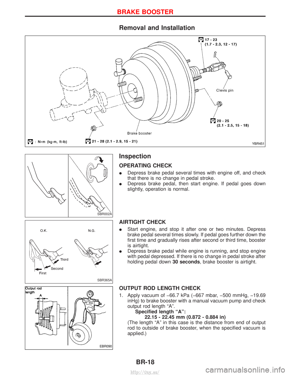
OPERATING CHECK
IDepress brake pedal several times with engine off, and check
that there is no change in pedal stroke.
I Depress brake pedal, then start engine. If pedal goes down
slightly, operation is normal.
AIRTIGHT CHECK
IStart engine, and stop it after one or two minutes. Depress
brake pedal several times slowly. If pedal goes further down the
first time and gradually rises after second or third time, booster
is airtight.
I Depress brake pedal while engine is running, and stop engine
with pedal depressed. If there is no change in pedal stroke after
holding pedal down 30 seconds, brake booster is airtight.
OUTPUT ROD LENGTH CHECK
1. Apply vacuum of þ66.7 kPa (þ667 mbar, þ500 mmHg, þ19.69
inHg) to brake booster with a manual vacuum pump and check
output rod length ªAº.Specified length ªAº: 22.15 - 22.45 mm (0.872 - 0.884 in)
(The length ªAº in this case is the distance from end of output
rod to outside of brake booster, when the specified vacuum is
applied.)
YBR451
SBR002A
SBR365A
EBR090
BRAKE BOOSTER
BR-18
http://vnx.su/
Page 1304 of 1833
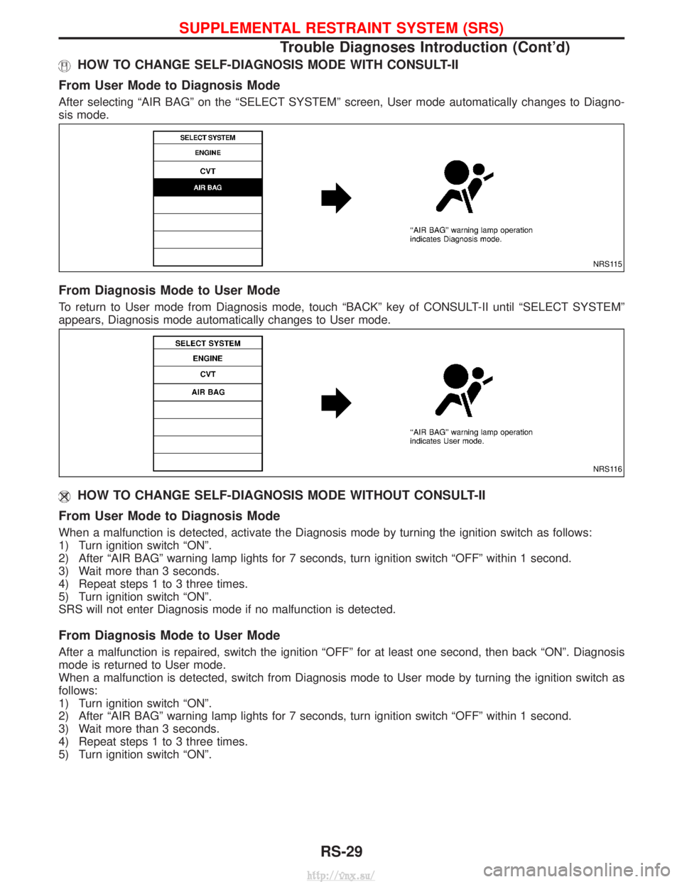
HOW TO CHANGE SELF-DIAGNOSIS MODE WITH CONSULT-II
From User Mode to Diagnosis Mode
After selecting ªAIR BAGº on the ªSELECT SYSTEMº screen, User mode automatically changes to Diagno-
sis mode.
From Diagnosis Mode to User Mode
To return to User mode from Diagnosis mode, touch ªBACKº key of CONSULT-II until ªSELECT SYSTEMº
appears, Diagnosis mode automatically changes to User mode.
HOW TO CHANGE SELF-DIAGNOSIS MODE WITHOUT CONSULT-II
From User Mode to Diagnosis Mode
When a malfunction is detected, activate the Diagnosis mode by turning the ignition switch as follows:
1) Turn ignition switch ªONº.
2) After ªAIR BAGº warning lamp lights for 7 seconds, turn ignition switch ªOFFº within 1 second.
3) Wait more than 3 seconds.
4) Repeat steps 1 to 3 three times.
5) Turn ignition switch ªONº.
SRS will not enter Diagnosis mode if no malfunction is detected.
From Diagnosis Mode to User Mode
After a malfunction is repaired, switch the ignition ªOFFº for at least one second, then back ªONº. Diagnosis
mode is returned to User mode.
When a malfunction is detected, switch from Diagnosis mode to User mode by turning the ignition switch as
follows:
1) Turn ignition switch ªONº.
2) After ªAIR BAGº warning lamp lights for 7 seconds, turn ignition switch ªOFFº within 1 second.
3) Wait more than 3 seconds.
4) Repeat steps 1 to 3 three times.
5) Turn ignition switch ªONº.
NRS115
NRS116
SUPPLEMENTAL RESTRAINT SYSTEM (SRS)
Trouble Diagnoses Introduction (Cont'd)
RS-29
http://vnx.su/
Page 1430 of 1833
TROUBLE DIAGNOSES FOR ABNORMAL PRESSURE
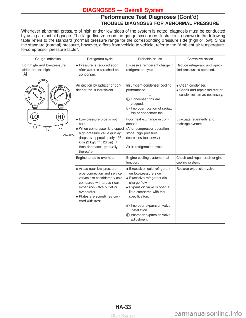
Whenever abnormal pressure of high and/or low sides of the system is noted, diagnosis must be conducted
by using a manifold gauge. The large-line zone on the gauge scale (see illustrations.) shown in the following
table refers to the standard (normal) pressure range for the corresponding pressure side (high or low). Since
the standard (normal) pressure, however, differs from vehicle to vehicle, refer to the ªAmbient air temperature-
to-compressor pressure tableº.
Gauge indicationRefrigerant cycleProbable causeCorrective action
Both high- and low-pressure
sides are too high.
AC359A
I Pressure is reduced soon
after water is splashed on
condenser. Excessive refrigerant charge in
refrigeration cycle
Reduce refrigerant until speci-
fied pressure is obtained.
Air suction by radiator or con-
denser fan is insufficient. Insufficient condenser cooling
performance
"
q
1Condenser fins are
clogged.
q
2Improper rotation of radiator
fan or condenser fan I
Clean condenser.
I Check and repair radiator or
condenser fan as necessary.
I Low-pressure pipe is not
cold.
I When compressor is stopped
high-pressure value quickly
drops by approximately 196
kPa (2 kg/cm
2, 28 psi). It
then decreases gradually
thereafter. Poor heat exchange in con-
denser
(After compressor operation
stops, high pressure
decreases too slowly.)
"
Air in refrigeration cycle Evacuate repeatedly and
recharge system.
Engine tends to overheat. Engine cooling systems mal- function.Check and repair each engine
cooling system.
I Areas near low-pressure
pipe connection and service
valves are considerably cold
compared with areas near
expansion valve outlet or
evaporator.
I Plates are sometimes cov-
ered with frost. I
Excessive liquid refrigerant
on low-pressure side
I Excessive refrigerant dis-
charge flow
I Expansion valve is open a
little compared with the
specification.
"
q
1Improper expansion valve
installation
q
2Improper expansion valve
adjustment Replace expansion valve.
DIAGNOSES Ð Overall System
Performance Test Diagnoses (Cont'd)
HA-33
http://vnx.su/
Page 1432 of 1833
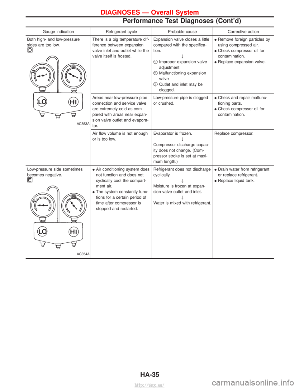
Gauge indicationRefrigerant cycleProbable causeCorrective action
Both high- and low-pressure
sides are too low.
AC353A
There is a big temperature dif-
ference between expansion
valve inlet and outlet while the
valve itself is frosted. Expansion valve closes a little
compared with the specifica-
tion.
"
q
1Improper expansion valve
adjustment
q
2Malfunctioning expansion
valve
q
3Outlet and inlet may be
clogged. I
Remove foreign particles by
using compressed air.
I Check compressor oil for
contamination.
I Replace expansion valve.
Areas near low-pressure pipe
connection and service valve
are extremely cold as com-
pared with areas near expan-
sion valve outlet and evapora-
tor. Low-pressure pipe is clogged
or crushed.
I
Check and repair malfunc-
tioning parts.
I Check compressor oil for
contamination.
Air flow volume is not enough
or is too low. Evaporator is frozen.
"
Compressor discharge capac-
ity does not change. (Com-
pressor stroke is set at maxi-
mum length.) Replace compressor.
Low-pressure side sometimes
becomes negative.
AC354A
I Air conditioning system does
not function and does not
cyclically cool the compart-
ment air.
I The system constantly func-
tions for a certain period of
time after compressor is
stopped and restarted. Refrigerant does not discharge
cyclically.
"
Moisture is frozen at expan-
sion valve outlet and inlet. "
Water is mixed with refrigerant. I
Drain water from refrigerant
or replace refrigerant.
I Replace liquid tank.
DIAGNOSES Ð Overall System
Performance Test Diagnoses (Cont'd)
HA-35
http://vnx.su/
Page 1627 of 1833
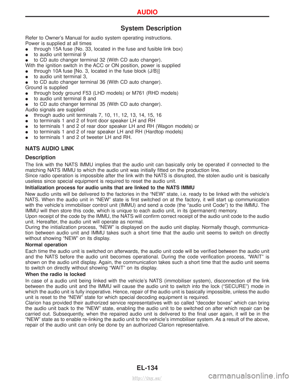
System Description
Refer to Owner's Manual for audio system operating instructions.
Power is supplied at all times
Ithrough 15A fuse (No. 33, located in the fuse and fusible link box)
I to audio unit terminal 9
I to CD auto changer terminal 32 (With CD auto changer).
With the ignition switch in the ACC or ON position, power is supplied
I through 10A fuse [No. 3, located in the fuse block (J/B)]
I to audio unit terminal 3,
I to CD auto changer terminal 36 (With CD auto changer).
Ground is supplied
I through body ground F53 (LHD models) or M761 (RHD models)
I to audio unit terminal 8 and
I to CD auto changer terminal 35 (With CD auto changer).
Audio signals are supplied
I through audio unit terminals 7, 10, 11, 12, 13, 14, 15, 16
I to terminals 1 and 2 of front door speaker LH and RH
I to terminals 1 and 2 of rear door speaker LH and RH (Wagon models) or
I to terminals 1 and 2 of rear speaker LH and RH (Hardtop models)
I to terminals 1 and 2 of tweeter LH and RH.
NATS AUDIO LINK
Description
The link with the NATS IMMU implies that the audio unit can basically only be operated if connected to the
matching NATS IMMU to which the audio unit was initially fitted on the production line.
Since radio operation is impossible after the link with the NATS is disrupted, the stolen audio unit is basically
useless since special equipment is required to reset the audio unit.
Initialization process for audio units that are linked to the NATS IMMU
New audio units will be delivered to the factories in the ªNEWº state, i.e. ready to be linked with the vehicle's
NATS. When the audio unit in ªNEWº state is first switched on at the factory, it will start up communication
with the vehicle's immobiliser control unit (IMMU) and send a code (the ªaudio unit Codeº) to the IMMU. The
IMMU will then store this code, which is unique to each audio unit, in its (permanent) memory.
Upon receipt of the code by the IMMU, the NATS will confirm correct receipt of the audio unit code to the audio
unit. Hereafter, the audio unit will operate as normal.
During the initialization process, ªNEWº is displayed on the audio unit display. Normally though, communica-
tion between audio unit and IMMU takes such a short time that the audio unit seems to switch on directly
without showing ªNEWº on its display.
Normal operation
Each time the audio unit is switched on afterwards, the audio unit code will be verified between the audio unit
and the NATS before the audio unit becomes operational. During the code verification process, ªWAITº is
shown on the audio unit display. Again, the communication takes such a short time that the audio unit seems
to switch on directly without showing ªWAITº on its display.
When the radio is locked
In case of a audio unit being linked with the vehicle's NATS (immobiliser system), disconnection of the link
between the audio unit and the IMMU will cause the audio unit to switch into the lock (ªSECUREº) mode in
which the audio unit is fully inoperative. Hence, repair of the audio unit is basically impossible, unless the audio
unit is reset to the ªNEWº state for which special decoding equipment is required.
Clarion has provided their authorized service representatives with so called ªdecoder boxesº which can bring
the audio unit back to the ªNEWº state, enabling the audio unit to be switched on after which repair can be
carried out. Subsequently, when the repaired audio unit is delivered to the final user again, it will be in the
ªNEWº state as to enable re-linking the audio unit to the vehicle's immobiliser system. As a result of the above,
repair of the audio unit can only be done by an authorized Clarion representative.
AUDIO
EL-134
http://vnx.su/
Page 1712 of 1833
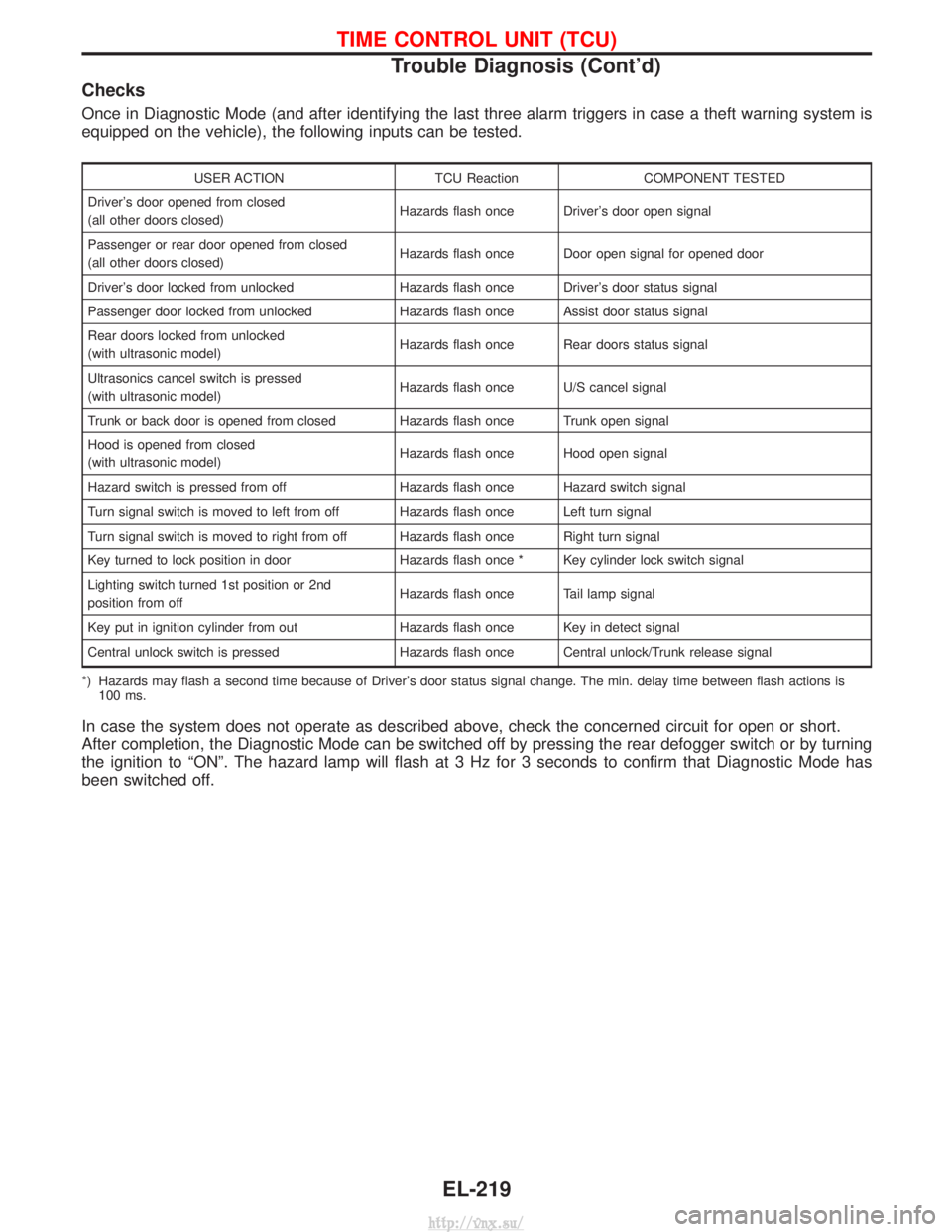
Checks
Once in Diagnostic Mode (and after identifying the last three alarm triggers in case a theft warning system is
equipped on the vehicle), the following inputs can be tested.
USER ACTIONTCU ReactionCOMPONENT TESTED
Driver's door opened from closed
(all other doors closed) Hazards flash once Driver's door open signal
Passenger or rear door opened from closed
(all other doors closed) Hazards flash once Door open signal for opened door
Driver's door locked from unlocked Hazards flash once Driver's door status signal
Passenger door locked from unlocked Hazards flash once Assist door status signal
Rear doors locked from unlocked
(with ultrasonic model) Hazards flash once Rear doors status signal
Ultrasonics cancel switch is pressed
(with ultrasonic model) Hazards flash once U/S cancel signal
Trunk or back door is opened from closed Hazards flash once Trunk open signal
Hood is opened from closed
(with ultrasonic model) Hazards flash once Hood open signal
Hazard switch is pressed from off Hazards flash once Hazard switch signal
Turn signal switch is moved to left from off Hazards flash once Left turn signal
Turn signal switch is moved to right from off Hazards flash once Right turn signal
Key turned to lock position in door Hazards flash once * Key cylinder lock switch signal
Lighting switch turned 1st position or 2nd
position from off Hazards flash once Tail lamp signal
Key put in ignition cylinder from out Hazards flash once Key in detect signal
Central unlock switch is pressed Hazards flash once Central unlock/Trunk release signal
*) Hazards may flash a second time because of Driver's door status signal change. The min. delay time between flash actions is 100 ms.
In case the system does not operate as described above, check the concerned circuit for open or short.
After completion, the Diagnostic Mode can be switched off by pressing the rear defogger switch or by turning
the ignition to ªONº. The hazard lamp will flash at 3 Hz for 3 seconds to confirm that Diagnostic Mode has
been switched off.
TIME CONTROL UNIT (TCU)
Trouble Diagnosis (Cont'd)
EL-219
http://vnx.su/