Page 1118 of 1833
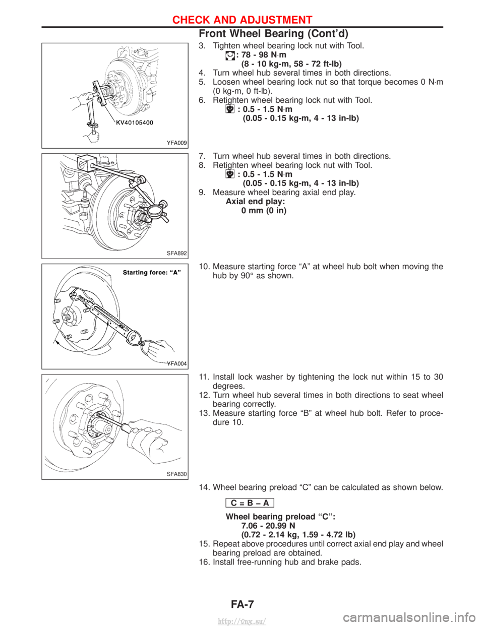
3. Tighten wheel bearing lock nut with Tool.
:78-98N×m
(8 - 10 kg-m, 58 - 72 ft-lb)
4. Turn wheel hub several times in both directions.
5. Loosen wheel bearing lock nut so that torque becomes 0 N ×m
(0 kg-m, 0 ft-lb).
6. Retighten wheel bearing lock nut with Tool.
: 0.5 - 1.5 N ×m
(0.05 - 0.15 kg-m,4-13 in-lb)
7. Turn wheel hub several times in both directions.
8. Retighten wheel bearing lock nut with Tool.
: 0.5 - 1.5 N ×m
(0.05 - 0.15 kg-m,4-13 in-lb)
9. Measure wheel bearing axial end play. Axial end play:0mm(0in)
10. Measure starting force ªAº at wheel hub bolt when moving the hub by 90É as shown.
11. Install lock washer by tightening the lock nut within 15 to 30 degrees.
12. Turn wheel hub several times in both directions to seat wheel bearing correctly.
13. Measure starting force ªBº at wheel hub bolt. Refer to proce- dure 10.
14. Wheel bearing preload ªCº can be calculated as shown below. C=BþA
Wheel bearing preload ªCº:7.06 - 20.99 N
(0.72 - 2.14 kg, 1.59 - 4.72 lb)
15. Repeat above procedures until correct axial end play and wheel bearing preload are obtained.
16. Install free-running hub and brake pads.
YFA009
SFA892
YFA004
SFA830
CHECK AND ADJUSTMENT
Front Wheel Bearing (Cont'd)
FA-7
http://vnx.su/
Page 1122 of 1833
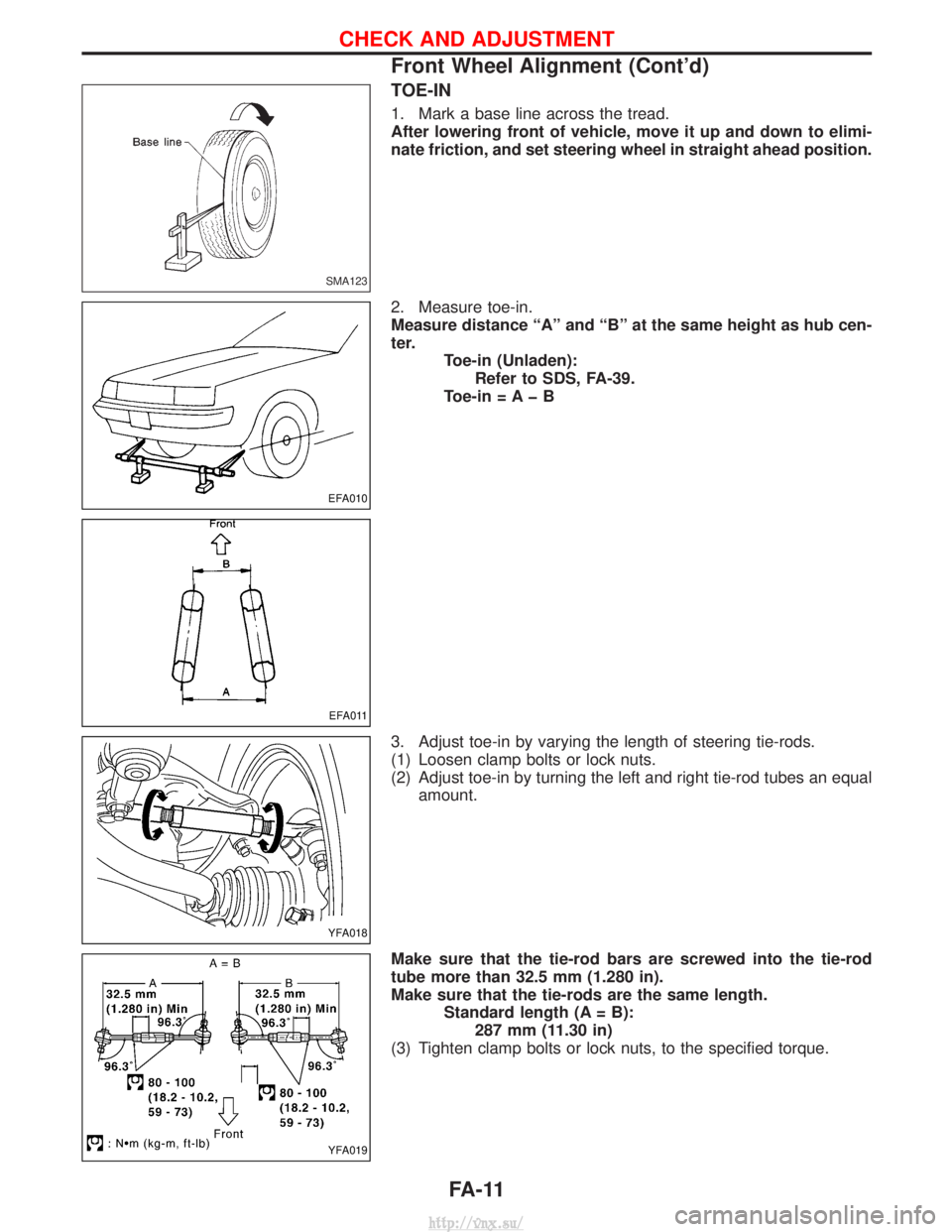
TOE-IN
1. Mark a base line across the tread.
After lowering front of vehicle, move it up and down to elimi-
nate friction, and set steering wheel in straight ahead position.
2. Measure toe-in.
Measure distance ªAº and ªBº at the same height as hub cen-
ter.Toe-in (Unladen):Refer to SDS, FA-39.
Toe-in = A þ B
3. Adjust toe-in by varying the length of steering tie-rods.
(1) Loosen clamp bolts or lock nuts.
(2) Adjust toe-in by turning the left and right tie-rod tubes an equal amount.
Make sure that the tie-rod bars are screwed into the tie-rod
tube more than 32.5 mm (1.280 in).
Make sure that the tie-rods are the same length. Standard length (A = B):287 mm (11.30 in)
(3) Tighten clamp bolts or lock nuts, to the specified torque.
SMA123
EFA010
EFA011
YFA018
YFA019
CHECK AND ADJUSTMENT
Front Wheel Alignment (Cont'd)
FA-11
http://vnx.su/
Page 1150 of 1833
Inspection and Adjustment
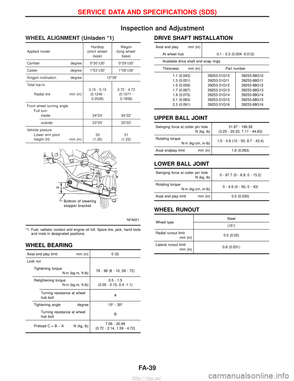
WHEEL ALIGNMENT (Unladen *1)
Applied modelHardtop
(short wheel- base) Wagon
(long wheel- base)
Camber degree 0É30¢ 30¢0É29¢ 30¢
Caster degree 1É53¢ 30¢1É58¢ 30¢
Kingpin inclination degree 12É39¢
Total toe-in
Radial tire mm (in)3.15 - 5.15
(0.1240 -0.2028) 2.72 - 4.72
(0.1071 -0.1858)
Front wheel turning angle Full turninside 34É24¢34É22¢
outside 33É35¢33É33¢
Vehicle posture Lower arm pivot
height (H) mm (in)33
(1.30) 31
(1.22)
NFA021
*1: Fuel, radiator coolant and engine oil full. Spare tire, jack, hand tools and mats in designated positions.
WHEEL BEARING
Axial end play limit mm (in)0 (0)
Lock nut Tightening torque N×m (kg-m, ft-lb) 78-98(8-10,58-72)
Retightening torque N×m (kg-m, ft-lb) 0.5 - 1.5
(0.05 - 0.15, 0.4 -1.1)
Turning resistance at wheel
hub bolt A
Tightening angle degree 15É - 30É
Turning resistance at wheel
hub bolt B
PreloadC=BþA N(kg, lb) 7.06 - 20.99
(0.72 - 2.14, 1.59 - 4.72)
DRIVE SHAFT INSTALLATION
Axial end play mm (in)
At wheel hub 0.1 - 0.3 (0.004 -0.012)
Available drive shaft end snap rings
Thickness mm (in) Part number 1.1 (0.043) 39253-31G10 39253-88G10
1.3 (0.051) 39253-31G11 39253-88G11
1.5 (0.059) 39253-31G12 39253-88G12
1.7 (0.067) 39253-31G13 39253-88G13
1.9 (0.075) 39253-31G14 39253-88G14
2.1 (0.083) 39253-31G15 39253-88G15
2.3 (0.091) 39253-31G16 39253-88G16
UPPER BALL JOINT
Swinging force at cotter pin hole N (kg, lb)31.87 - 199.38
(3.25 - 20.33, 7.17 - 44.83)
Rotating torque N×m (kg-cm, in-lb) 1.0 - 4.9 (10 - 50, 8.7 - 43.4)
Axial endplay limit mm (in) 1.6 (0.063)
LOWER BALL JOINT
Swinging force at cotter pin hole
N (kg, lb)0 - 67.7 (0 - 6.9, 0 - 15.2)
Rotating torque N×m (kg-cm, in-lb) 0 - 4.9 (0 - 50, 0 - 43)
Axial end play limit mm (in) 0.5 (0.020)
WHEEL RUNOUT
Wheel type Steel
(15² )
Radial runout limit mm (in) 0.5 (0.02)
Lateral runout limit mm (in) 0.8 (0.031)
SERVICE DATA AND SPECIFICATIONS (SDS)
FA-39
http://vnx.su/
Page 1153 of 1833
Precautions
IWhen installing each rubber part, final tightening must be car-
ried out under unladen condition* with tires on ground.
* Fuel, radiator coolant and engine oil full. Spare tire, jack,
hand tools and mats in designated positions.
I Use Tool when removing or installing brake tubes.
I If suspension or suspension parts are dismounted, check wheel
alignment and adjust if necessary.
I Do not jack up vehicle at lower link.
Preparation
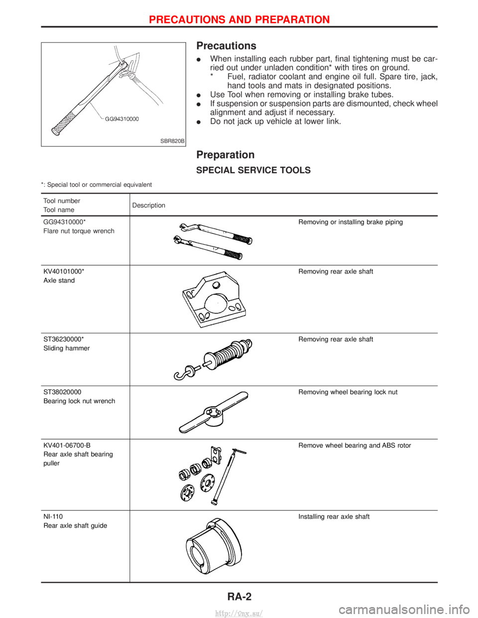
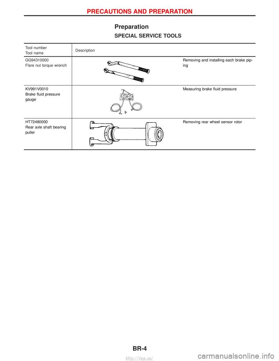
SPECIAL SERVICE TOOLS
*: Special tool or commercial equivalent
Tool number
Tool name Description
GG94310000*
Flare nut torque wrench
Removing or installing brake piping
KV40101000*
Axle stand
Removing rear axle shaft
ST36230000*
Sliding hammer
Removing rear axle shaft
ST38020000
Bearing lock nut wrench
Removing wheel bearing lock nut
KV401-06700-B
Rear axle shaft bearing
puller
Remove wheel bearing and ABS rotor
NI-110
Rear axle shaft guide
Installing rear axle shaft
SBR820B
PRECAUTIONS AND PREPARATION
RA-2
http://vnx.su/
Page 1156 of 1833
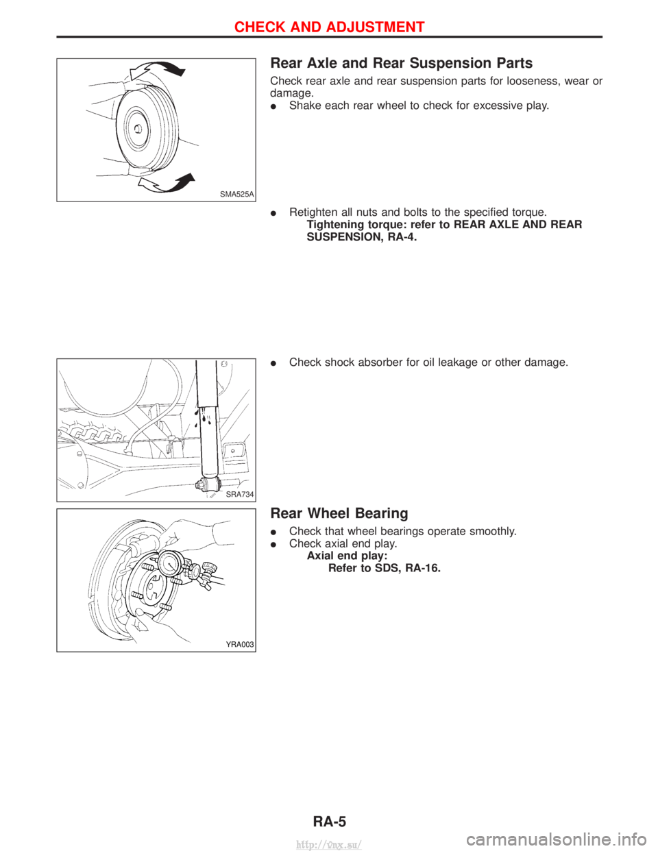
Rear Axle and Rear Suspension Parts
Check rear axle and rear suspension parts for looseness, wear or
damage.
IShake each rear wheel to check for excessive play.
I Retighten all nuts and bolts to the specified torque.
Tightening torque: refer to REAR AXLE AND REAR
SUSPENSION, RA-4.
I Check shock absorber for oil leakage or other damage.
Rear Wheel Bearing
ICheck that wheel bearings operate smoothly.
I Check axial end play.
Axial end play: Refer to SDS, RA-16.
SMA525A
SRA734
YRA003
CHECK AND ADJUSTMENT
RA-5
http://vnx.su/
Page 1160 of 1833
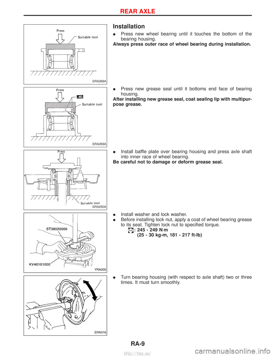
Installation
IPress new wheel bearing until it touches the bottom of the
bearing housing.
Always press outer race of wheel bearing during installation.
I Press new grease seal until it bottoms end face of bearing
housing.
After installing new grease seal, coat sealing lip with multipur-
pose grease.
I Install baffle plate over bearing housing and press axle shaft
into inner race of wheel bearing.
Be careful not to damage or deform grease seal.
I Install washer and lock washer.
I Before installing lock nut, apply a coat of wheel bearing grease
to its seat. Tighten lock nut to specified torque.
: 245 - 249 N ×m
(25 - 30 kg-m, 181 - 217 ft-lb)
I Turn bearing housing (with respect to axle shaft) two or three
times. It must turn smoothly.
SRA288A
SRA289A
SRA290A
YRA005
ERA016
REAR AXLE
RA-9
http://vnx.su/
Page 1170 of 1833
Supplement Restraint System (SRS) ªAIR BAGº
and ªSEAT BELT PRE-TENSIONERº
The Supplemental Restraint System ªAir Bagº and ªSeat Belt Pre-tensionerº, used along with a seat belt, help
to reduce the risk or severity or injury to the driver and front passenger in a collision. The Supplemental
Restraint System consists of an air bag module (located in the center of the steering wheel and on the instru-
ment panel on the passenger side, where fitted), seat belt pre-tensioners, a diagnosis sensor unit, warning
lamp, wiring harness and spiral cable. Information necessary to service the system safely is included in the
BT sectionof this Service Manual.
WARNING:
I To avoid rendering the SRS inoperative (which could increase the risk of personal injury or death
in the event of a collision which would result in air bag inflation), all maintenance must be per-
formed by an authorized NISSAN dealer.
I Improper maintenance, including incorrect removal and installation of the SRS, can lead to per-
sonal injury caused by unintentional activation of the system.
I Do not use electrical test equipment on any circuit related to the SRS unless instructed to in this
Service Manual. SRS wiring harnesses (except ªSEAT BELT-TENSIONERº connector) can be iden-
tified with yellow harness connector and with yellow harness protector or yellow insulation tape
before the harness connectors.
Precautions
IUse only ªDOT 4º fluid from a sealed container.
I Never reuse drained brake fluid.
I Be careful not to splash brake fluid on painted areas; it
may cause paint damage. If brake fluid is splashed on
painted areas, wash it away with water immediately.
I To clean master cylinder parts, disc brake caliper parts or
wheel cylinder parts, use clean brake fluid.
I Never use mineral oils such as Petrol or kerosene. They
will ruin rubber parts of hydraulic system.
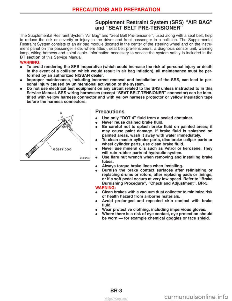
I Use flare nut wrench when removing and installing brake
tubes.
I Always torque brake lines when installing.
I Burnish the brake contact surfaces after refinishing or
replacing drums or rotors, after replacing pads or linings,
or if a soft pedal occurs at very low speed. Refer to ªBrake
Burnishing Procedureº, ªCheck and Adjustmentº, BR-5.
WARNING:
I Clean brakes with a vacuum dust collector to minimize risk
of health hazard from airborne materials.
I Avoid prolonged and repeated skin contact with brake
fluid.
I Wear protective clothing, including impervious gloves.
I Where there is a risk of eye contact, eye protection should
be worn Ð for example chemical goggles or face shield.
YBR293
PRECAUTIONS AND PREPARATION
BR-3
http://vnx.su/
Page 1171 of 1833
Preparation
SPECIAL SERVICE TOOLS
Tool number
Tool nameDescription
GG94310000
Flare nut torque wrench
Removing and installing each brake pip-
ing
KV991V0010
Brake fluid pressure
gauge
Measuring brake fluid pressure
HT72480000
Rear axle shaft bearing
puller
Removing rear wheel sensor rotor
PRECAUTIONS AND PREPARATION
BR-4
http://vnx.su/