Page 1517 of 1833

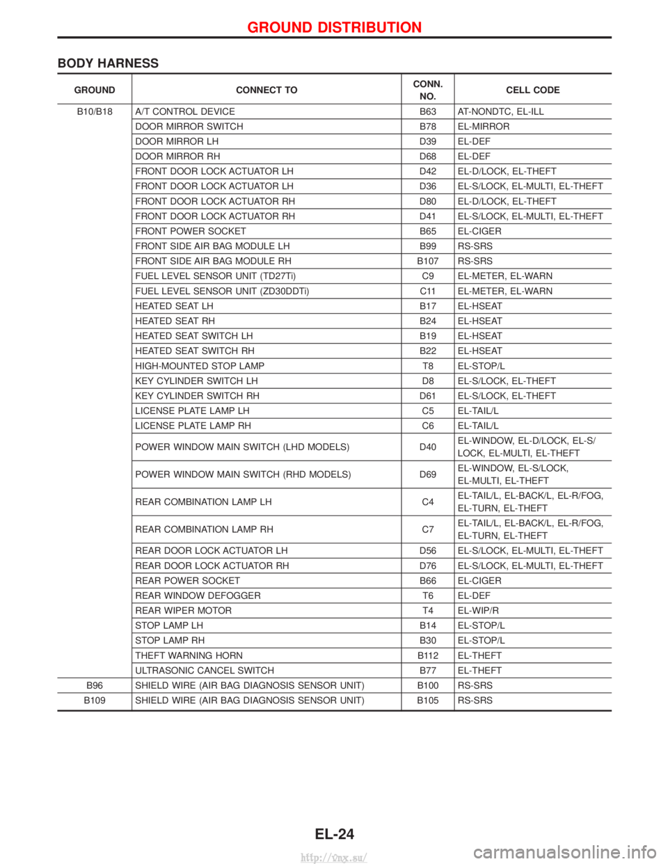
BODY HARNESS
GROUNDCONNECT TO CONN.
NO. CELL CODE
B10/B18 A/T CONTROL DEVICE B63 AT-NONDTC, EL-ILL
DOOR MIRROR SWITCH B78 EL-MIRROR
DOOR MIRROR LH D39 EL-DEF
DOOR MIRROR RH D68 EL-DEF
FRONT DOOR LOCK ACTUATOR LH D42 EL-D/LOCK, EL-THEFT
FRONT DOOR LOCK ACTUATOR LH D36 EL-S/LOCK, EL-MULTI, EL-THEFT
FRONT DOOR LOCK ACTUATOR RH D80 EL-D/LOCK, EL-THEFT
FRONT DOOR LOCK ACTUATOR RH D41 EL-S/LOCK, EL-MULTI, EL-THEFT
FRONT POWER SOCKET B65 EL-CIGER
FRONT SIDE AIR BAG MODULE LH B99 RS-SRS
FRONT SIDE AIR BAG MODULE RH B107 RS-SRS
FUEL LEVEL SENSOR UNIT (TD27Ti) C9 EL-METER, EL-WARN
FUEL LEVEL SENSOR UNIT (ZD30DDTi) C11 EL-METER, EL-WARN
HEATED SEAT LH B17 EL-HSEAT
HEATED SEAT RH B24 EL-HSEAT
HEATED SEAT SWITCH LH B19 EL-HSEAT
HEATED SEAT SWITCH RH B22 EL-HSEAT
HIGH-MOUNTED STOP LAMP T8 EL-STOP/L
KEY CYLINDER SWITCH LH D8 EL-S/LOCK, EL-THEFT
KEY CYLINDER SWITCH RH D61 EL-S/LOCK, EL-THEFT
LICENSE PLATE LAMP LH C5 EL-TAIL/L
LICENSE PLATE LAMP RH C6 EL-TAIL/L
POWER WINDOW MAIN SWITCH (LHD MODELS) D40EL-WINDOW, EL-D/LOCK, EL-S/
LOCK, EL-MULTI, EL-THEFT
POWER WINDOW MAIN SWITCH (RHD MODELS) D69EL-WINDOW, EL-S/LOCK,
EL-MULTI, EL-THEFT
REAR COMBINATION LAMP LH C4EL-TAIL/L, EL-BACK/L, EL-R/FOG,
EL-TURN, EL-THEFT
REAR COMBINATION LAMP RH C7EL-TAIL/L, EL-BACK/L, EL-R/FOG,
EL-TURN, EL-THEFT
REAR DOOR LOCK ACTUATOR LH D56 EL-S/LOCK, EL-MULTI, EL-THEFT
REAR DOOR LOCK ACTUATOR RH D76 EL-S/LOCK, EL-MULTI, EL-THEFT
REAR POWER SOCKET B66 EL-CIGER
REAR WINDOW DEFOGGER T6 EL-DEF
REAR WIPER MOTOR T4 EL-WIP/R
STOP LAMP LH B14 EL-STOP/L
STOP LAMP RH B30 EL-STOP/L
THEFT WARNING HORN B112 EL-THEFT
ULTRASONIC CANCEL SWITCH B77 EL-THEFT
B96 SHIELD WIRE (AIR BAG DIAGNOSIS SENSOR UNIT) B100 RS-SRS
B109 SHIELD WIRE (AIR BAG DIAGNOSIS SENSOR UNIT) B105 RS-SRS
GROUND DISTRIBUTION
EL-24
http://vnx.su/
Page 1553 of 1833
or M33, M754 (RHD models).
Ground is supplied to terminal 4 of each rear combination lamp through body grounds B10 and B18.
With power and ground supplied, the time control unit controls the flashing of the hazard warning lamps, and
time control unit supplies power to combination meter terminals 7 or 33, to flash hazard warning indicator.
HAZARD REMINDER OPERATION FOR MULTI-REMOTE CONTROL SYSTEM
When the doors are locked or unlocked by multi-remote controller, time control unit controls turn lamps haz-
ard reminder flashes as follows.
ILocked operation: Flash once
I Unlock operation: Flash twice
EXTERIOR LAMP
System Description (Cont'd)
EL-60
http://vnx.su/
Page 1559 of 1833

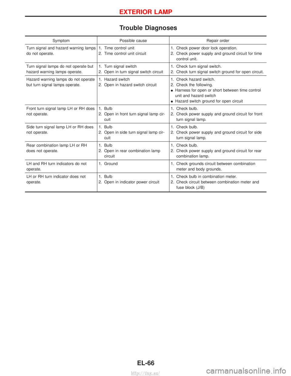
Trouble Diagnoses
SymptomPossible cause Repair order
Turn signal and hazard warning lamps
do not operate. 1. Time control unit
2. Time control unit circuit1. Check power door lock operation.
2. Check power supply and ground circuit for time
control unit.
Turn signal lamps do not operate but
hazard warning lamps operate. 1. Turn signal switch
2. Open in turn signal switch circuit1. Check turn signal switch.
2. Check turn signal switch ground for open circuit.
Hazard warning lamps do not operate
but turn signal lamps operate. 1. Hazard switch
2. Open in hazard switch circuit1. Check hazard switch.
2. Check the following.
I
Harness for open or short between time control
unit and hazard switch
I Hazard switch ground for open circuit
Front turn signal lamp LH or RH does
not operate. 1. Bulb
2. Open in front turn signal lamp cir-
cuit 1. Check bulb.
2. Check power supply and ground circuit for front
turn signal lamp.
Side turn signal lamp LH or RH does
not operate. 1. Bulb
2. Open in side turn signal lamp cir-
cuit 1. Check bulb.
2. Check power supply and ground circuit for side
turn signal lamp.
Rear combination lamp LH or RH
does not operate. 1. Bulb
2. Open in rear combination lamp
circuit 1. Check bulb.
2. Check power supply and ground circuit for rear
combination lamp.
LH and RH turn indicators do not
operate. 1. Ground
1. Check grounds circuit between combination
meter and body grounds.
LH or RH turn indicator does not
operate. 1. Bulb
2. Open in indicator power circuit1. Check bulb in combination meter.
2. Check circuit between combination meter and
fuse block (J/B)
EXTERIOR LAMP
EL-66
http://vnx.su/
Page 1565 of 1833
![NISSAN TERRANO 2004 Service Repair Manual System Description
POWER SUPPLY AND GROUND
Power is supplied at all times:
Ithrough 15A fuse [No. 5, located in the fuse block (J/B)]
I to time control unit terminal U09,
I through 10A fuse [No. 16, l NISSAN TERRANO 2004 Service Repair Manual System Description
POWER SUPPLY AND GROUND
Power is supplied at all times:
Ithrough 15A fuse [No. 5, located in the fuse block (J/B)]
I to time control unit terminal U09,
I through 10A fuse [No. 16, l](/manual-img/5/57394/w960_57394-1564.png)
System Description
POWER SUPPLY AND GROUND
Power is supplied at all times:
Ithrough 15A fuse [No. 5, located in the fuse block (J/B)]
I to time control unit terminal U09,
I through 10A fuse [No. 16, located in the fuse block (J/B)]
I to front interior lamp terminal 1,
I to rear interior lamp terminal 1 (Wagon models)
I to rear room lamp terminal 2 (Hardtop models)
I to sunroof switch and map lamps terminal 3 (with sunroof),
I to map lamp terminal 2 (without sunroof).
Ground is supplied:
I through body grounds terminals F36, F47 (LHD models) or M33, M754 (RHD models).
I through fuse block terminal MM2
I to time control unit terminal U16
When the driver side door is opened, ground is supplied:
I through driver side door switch case ground and terminal 1, and
I through fuse block terminal B07
I to time control unit terminal U06
When any door is opened, ground is supplied:
I through case ground and terminal 1 of each door switch,
I through fuse block terminal B01
I to time control unit terminal U07.
When the driver side door is unlocked by the door lock/unlock switch, the time control unit receives a ground
signal:
I through body grounds B10 and B18
I to power window main switch terminal 3
I from power window main switch terminal 7
I to time control unit terminal U37.
When a signal, or combination of signals is received by the time control unit, ground is supplied:
I through time control unit terminal U12 and fuse block terminal R01
I to front interior room lamp terminal 2.
I to rear interior lamp terminal 2 (Wagon models).
I to rear interior room lamp terminal 1 (Hardtop models).
With power and ground supplied, the interior room lamps illuminate when the lamp switch is in ªDOORº posi-
tion.
SWITCH OPERATION
When interior room lamp switch is in ªONº position, ground is supplied:
I through front interior lamp case ground.
I through rear interior lamp case ground (Wagon models).
When sunroof switch and map lamps (with sunroof) is ON, ground is supplied:
I through body grounds F36, F47 (LHD models) or M33, M754 (RHD models)
I through fuse block terminal MM2 and R03
I to sunroof switch map lamps terminal 2.
When map lamp (without sunroof) is ON, ground is supplied:
I through body grounds F36, F47 (LHD models) or M33, M754 (RHD models)
I through fuse block terminal MM2 and R03
I to map lamp terminal 1.
With power and ground supplied, the interior room lamps, map lamps illuminate.
INTERIOR ROOM LAMP TIMER OPERATION
When interior room lamp switch is in the ªDOORº position, the time control unit keeps the interior room lamp
illuminated for about 30 seconds when:
I unlock signal is supplied from door lock/unlock switch while all doors are closed
I unlock signal is supplied from remote controller or door key cylinder while all doors are closed
I driver's door is opened and then closed
The timer is canceled when:
I driver's door is locked,
INTERIOR LAMP
EL-72
http://vnx.su/
Page 1571 of 1833
Trouble Diagnoses
SYMPTOM CHART
SymptomDiagnoses service procedure
Interior room lamp timer does not operate. 1. Preliminary check.
2. Check ignition signal.
3. Check driver side door switch.
4. Check door lock/unlock switch.
5. Check other door switch.
Interior room lamp timer cannot be cancelled. 1. Preliminary check.
2. Check ignition signal.
3. Check driver side door switch.
4. Check door lock/unlock switch.
PRELIMINARY CHECK (Power supply and ground
circuit check)
Main power supply circuit check
Terminals Ignition switch position
!@ LOCK ACC ON
U09GroundBattery
voltage Battery
voltage Battery
voltage
Ground circuit check
Terminals Continuity
U16- GroundYes
IGNITION SWITCH ªONº CIRCUIT CHECK
TerminalsIgnition switch position
!@ OFFACC ON
U01Ground 0V0V Battery voltage
If NG, check the following.
I10A fuse [No.
26, located in the fuse block (J/B)]
IHarness for open or short
YEL299D
YEL300D
YEL319D
INTERIOR LAMP
EL-78
http://vnx.su/
Page 1572 of 1833
DRIVER SIDE DOOR SWITCH CHECK
CHECK DOOR SWITCH INPUT SIGNAL.
Check voltage between fuse block (J/B)
and ground.
NG
EOKDoor switch is OK.
CHECK DOOR SWITCH.
1. Disconnect door switch connector.
2. Check continuity between door switch terminal 1 and ground.
OK
ENG Replace door switch.
Check the following.
IDoor switch case ground condition
I Harness for open or short between con-
trol unit and door switch
Termi-
nals Condition Voltage (V)
Driver
side door
B07Opened 0 Closed Approx. 12
Terminals Condition Continuity
Door
switch q
1-
ground Closed No
Open Yes
YEL874E
YEL875E
H
H
INTERIOR LAMP
Trouble Diagnoses (Cont'd)
EL-79
http://vnx.su/
Page 1573 of 1833
DOOR LOCK/UNLOCK SWITCH CHECK
CHECK DOOR LOCK/UNLOCK SWITCH
INPUT SIGNAL.
Check voltage between time control unit
connector terminal
U37and ground.
NG
EOKDoor lock/unlock switch is
OK.
CHECK DOOR LOCK/UNLOCK SWITCH.
1. Disconnect door lock/unlock switch
connector.
2. Check continuity between door lock/ unlock switch terminals.
OK
ENG Replace door lock/unlock
switch.
Check the following:
IDoor lock/unlock switch ground circuit.
I Harness for open or short-circuit
between control unit and door lock/
unlock switch
Terminals
ConditionVoltage
(V)
!@
U37Ground LockedApprox.
12
(Approx. 20 sec.)
Unlocked 0
Terminals Condition Continuity
q
7-q3Locked
No
Unlocked Yes
YEL876E
YEL877E
H
H
INTERIOR LAMP
Trouble Diagnoses (Cont'd)
EL-80
http://vnx.su/
Page 1574 of 1833
OTHER DOOR SWITCH CHECK
CHECK DOOR SWITCH INPUT SIGNAL.
Check voltage between fuse block (J/B)
and ground.
NG
EOKDoor switch is OK.
CHECK DOOR SWITCH.
1. Disconnect door switch connector.
2. Check continuity between door switch terminals.
OK
ENG Replace door switch.
Check the following.
IDoor switch ground condition
I Harness for open or short between con-
trol unit and door switch
Termi-
nals Condition Voltage (V)
Other
door
B01Opened 0 Closed Approx. 12
Terminals Condition Continuity
Other
door
switches q
1-
ground Closed No
Open Yes
YEL878E
YEL879E
H
H
INTERIOR LAMP
Trouble Diagnoses (Cont'd)
EL-81
http://vnx.su/