2004 NISSAN TERRANO ECU
[x] Cancel search: ECUPage 72 of 1833
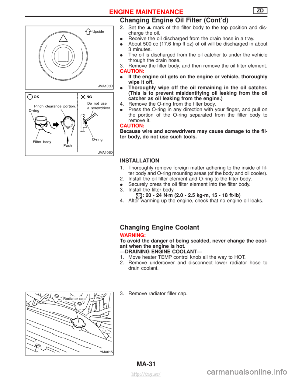
2. Set theGmark of the filter body to the top position and dis-
charge the oil.
I Receive the oil discharged from the drain hose in a tray.
I About 500 cc (17.6 Imp fl oz) of oil will be discharged in about
3 minutes.
I The oil is discharged from the oil catcher to under the vehicle
through the drain hose.
3. Remove the filter body, and then remove the oil filter element.
CAUTION:
I If the engine oil gets on the engine or vehicle, thoroughly
wipe it off.
I Thoroughly wipe off the oil remaining in the oil catcher.
(This is to prevent misidentifying oil leaking from the oil
catcher as oil leaking from the engine.)
4. Remove the O-ring from the filter body.
I Press the O-ring in any direction with your finger, and pull on
the portion of the O-ring separated from the filter body to
remove it.
CAUTION:
Because wire and screwdrivers may cause damage to the fil-
ter body, do not use such tools.
INSTALLATION
1. Thoroughly remove foreign matter adhering to the inside of fil- ter body and O-ring mounting areas (of the body and oil cooler).
2. Install the oil filter element and O-ring to the filter body.
I Securely press the oil filter element into the filter body.
3. Install the filter body.
:20-24N ×m (2.0 - 2.5 kg-m, 15 - 18 ft-lb)
4. After warming up the engine, check that no engine oil leaks.
Changing Engine Coolant
WARNING:
To avoid the danger of being scalded, never change the cool-
ant when the engine is hot.
ÐDRAINING ENGINE COOLANTÐ
1. Move heater TEMP control knob all the way to HOT.
2. Remove undercover and disconnect lower radiator hose to drain coolant.
3. Remove radiator filler cap.
JMA105D
JMA106D
YMA015
ENGINE MAINTENANCEZD
Changing Engine Oil Filter (Cont'd)
MA-31
http://vnx.su/
Page 85 of 1833
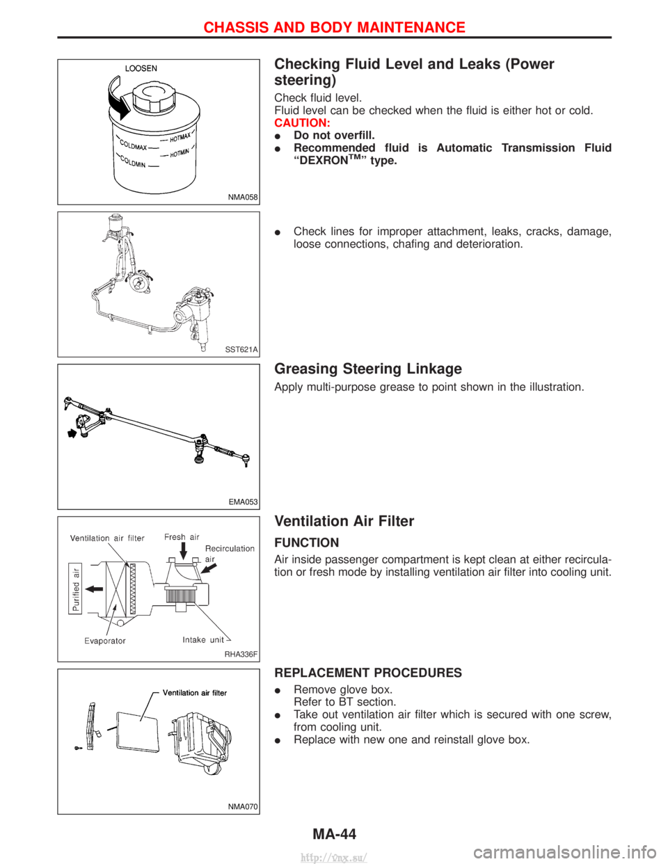
Checking Fluid Level and Leaks (Power
steering)
Check fluid level.
Fluid level can be checked when the fluid is either hot or cold.
CAUTION:
IDo not overfill.
I Recommended fluid is Automatic Transmission Fluid
ªDEXRON
TMº type.
I Check lines for improper attachment, leaks, cracks, damage,
loose connections, chafing and deterioration.
Greasing Steering Linkage
Apply multi-purpose grease to point shown in the illustration.
Ventilation Air Filter
FUNCTION
Air inside passenger compartment is kept clean at either recircula-
tion or fresh mode by installing ventilation air filter into cooling unit.
REPLACEMENT PROCEDURES
IRemove glove box.
Refer to BT section.
I Take out ventilation air filter which is secured with one screw,
from cooling unit.
I Replace with new one and reinstall glove box.
NMA058
SST621A
EMA053
RHA336F
NMA070
CHASSIS AND BODY MAINTENANCE
MA-44
http://vnx.su/
Page 122 of 1833
3. Remove injection tube and injection nozzle assembly. Refer toEC section, ªInjection Tube and Injection Nozzleº in ªBASIC
SERVICE PROCEDUREº.
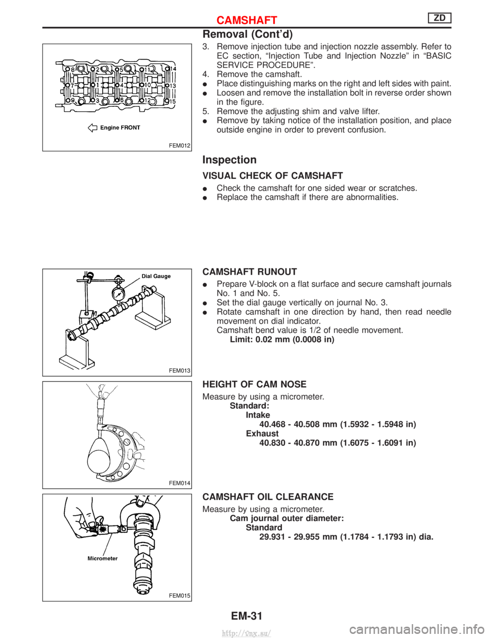
4. Remove the camshaft.
I Place distinguishing marks on the right and left sides with paint.
I Loosen and remove the installation bolt in reverse order shown
in the figure.
5. Remove the adjusting shim and valve lifter.
I Remove by taking notice of the installation position, and place
outside engine in order to prevent confusion.
Inspection
VISUAL CHECK OF CAMSHAFT
ICheck the camshaft for one sided wear or scratches.
I Replace the camshaft if there are abnormalities.
CAMSHAFT RUNOUT
IPrepare V-block on a flat surface and secure camshaft journals
No. 1 and No. 5.
I Set the dial gauge vertically on journal No. 3.
I Rotate camshaft in one direction by hand, then read needle
movement on dial indicator.
Camshaft bend value is 1/2 of needle movement.
Limit: 0.02 mm (0.0008 in)
HEIGHT OF CAM NOSE
Measure by using a micrometer. Standard:Intake40.468 - 40.508 mm (1.5932 - 1.5948 in)
Exhaust 40.830 - 40.870 mm (1.6075 - 1.6091 in)
CAMSHAFT OIL CLEARANCE
Measure by using a micrometer. Cam journal outer diameter:Standard29.931 - 29.955 mm (1.1784 - 1.1793 in) dia.
FEM012
FEM013
FEM014
FEM015
CAMSHAFTZD
Removal (Cont'd)
EM-31
http://vnx.su/
Page 127 of 1833

5. While referring to the figure, measure the valve clearance in thecircled area of the table below.
Measuring point No. 1 No. 2 No. 3 No. 4
INT EXH INT EXH INT EXH INT EXH
When the No. 4
cylinder is in the
TDC qq qq
6. If the valve clearance is outside the specification, adjust as fol-
lows.
Adjustments
IRemove the adjusting shim for parts which are outside the
specified valve clearance.
1. Remove the spill tube.
2. Extract the engine oil on the upper side of the cylinder head (for the air gun used in step 7).
3. Rotate the crankshaft to face the cam for adjusting shims that are to be removed upward.
4. Grip the camshaft with camshaft pliers (SST), the using the camshaft as a support point, push the adjusting shim downward
to compress the valve spring.
CAUTION:
Do not damage the camshaft, cylinder head, or the outer cir-
cumference of the valve lifter.
5. With the valve spring in a compressed state, remove the cam- shaft pliers (SST) by securely setting the outer circumference
of the valve lifter with the end of the lifter stopper (SST).
I Hold the lifter stopper by hand until the shim is removed.
CAUTION:
Do not retrieve the camshaft pliers forcefully, as the camshaft
will be damaged.
6. Move the rounded hole of the adjusting shim to the front with a very thin screwdriver.
I When the adjusting shim on the valve lifter will not rotate
smoothly, restart from step 4 with the end of the lifter stopper
(SST) touching the adjusting shim.
7. Remove the adjusting shim from the valve lifter by blowing air through the rounded hole of the shim with an air gun.
CAUTION:
To prevent any remaining oil from being blown around, thor-
oughly wipe the area clean and wear protective goggles.
FEM027
FEM028
FEM029
FEM030
VALVE CLEARANCE INSPECTIONS AND ADJUSTMENTSZD
Inspection (Cont'd)
EM-36
http://vnx.su/
Page 155 of 1833

Engine room (Left)
3. Remove air duct and air cleaner case.
4. Disconnect vacuum hose to the vehicle on the engine.
5. Disconnect harness connectors from alternator and air com-pressor.
6. Remove alternator.
7. After removing refrigerant, remove pipes of air compressor and inlet/outlet.
8. Disconnect heating hose, install blank cap to hose to prevent coolant from leaking.
9. Remove heating pipe.
10. Remove heat insulator.
11. Remove catalytic converter.
Engine room (Right)
12. Remove power steering reservoir tank from bracket, and fix it to the vehicle with a rope.
CAUTION:
Keep the reservoir tank level when fixing to prevent oil leak.
13. Remove fuel feed and return hoses.
CAUTION:
Install blank caps immediately to avoid fuel leakage.
14. Remove all harness connectors on the engine, and move har- nesses to the side of the vehicle.
Vehicle underfloor
15. Remove starter motor.
16. Detach A/T oil cooler pipes from oil pan. (A/T model)
17. Remove rear propeller shaft.
18. Remove mounting bolts to secure the engine to transmission.
1) Remove torque converter installation bolt. (A/T model)
2) Lift transmission bottom with transmission jack, and removerear mount members from the vehicle.
3) Lower transmission with the jack, and remove upper mounting bolts securing the engine to transmission.
4) Lift transmission with the jack, and reinstall rear mount mem- bers to the vehicle.
5) Position the jack to the front side of transmission.
6) Remove remaining mounting bolts securing the engine to trans- mission.
Removal operation
19. Remove air conditioner high pressure pipes at the rear of theengine room.
I This is due to some inconvenience in the rear slinger installa-
tion.
20. Install the engine slingers (standard service part) to front-left and rear-right.
:25-28N ×m (2.5 - 2.9 kg-m, 18 - 20 ft-lb)
WARNING:
For engines without engine slingers, attach proper slingers
and bolts described in the PARTS CATALOG.
FEM082
ENGINE REMOVALZD
Removal (Cont'd)
EM-64
http://vnx.su/
Page 156 of 1833
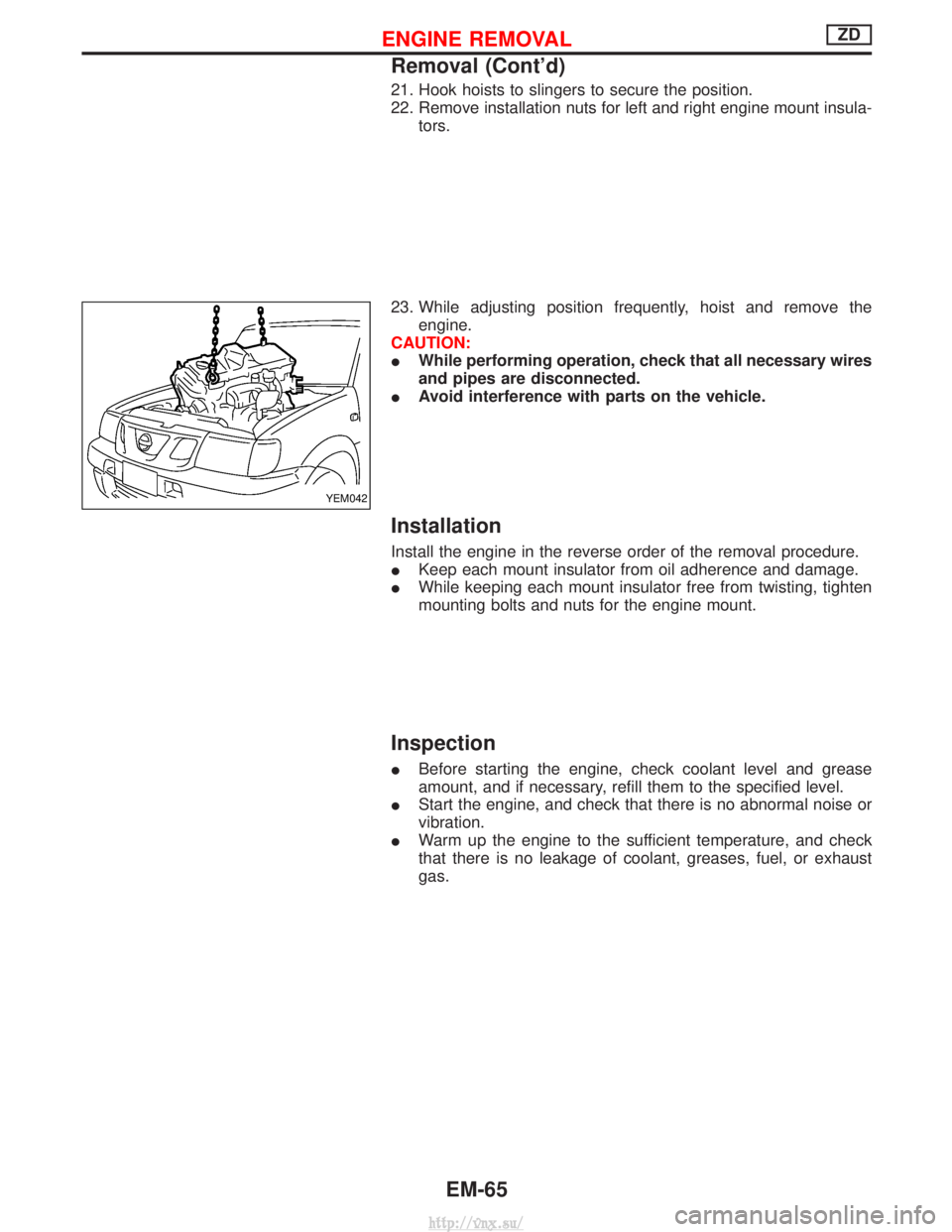
21. Hook hoists to slingers to secure the position.
22. Remove installation nuts for left and right engine mount insula-tors.
23. While adjusting position frequently, hoist and remove the engine.
CAUTION:
I While performing operation, check that all necessary wires
and pipes are disconnected.
I Avoid interference with parts on the vehicle.
Installation
Install the engine in the reverse order of the removal procedure.
IKeep each mount insulator from oil adherence and damage.
I While keeping each mount insulator free from twisting, tighten
mounting bolts and nuts for the engine mount.
Inspection
IBefore starting the engine, check coolant level and grease
amount, and if necessary, refill them to the specified level.
I Start the engine, and check that there is no abnormal noise or
vibration.
I Warm up the engine to the sufficient temperature, and check
that there is no leakage of coolant, greases, fuel, or exhaust
gas.
YEM042
ENGINE REMOVALZD
Removal (Cont'd)
EM-65
http://vnx.su/
Page 158 of 1833
Selection Procedure for Selective Part
Combination
LocationSelective part combination ItemMethod
Cylinder block - piston Piston and piston assembly
(Part No. is given to a piston and piston pin as a set.) Piston grade (Piston outer
diameter) Refer to ªSelective combination
chartº.
IIdentification grade stamped on each part represents initial
dimension of new part. This grade will not be applied to a
reused part.
I Measure correct dimensions of a reused or modified part, then
refer to ªSelective combination chartº in this manual to identify
the grade.
I Refer to the applicable pages for measurement method for
each part, standards for reuse, and selecting method for selec-
tive part combination.
Disassembly
1. Remove engine assembly from vehicle.
Refer to EM-63, ªENGINE REMOVALº.
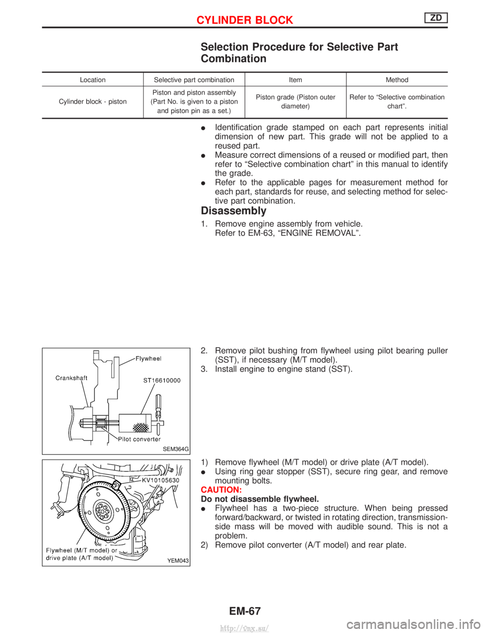
2. Remove pilot bushing from flywheel using pilot bearing puller (SST), if necessary (M/T model).
3. Install engine to engine stand (SST).
1) Remove flywheel (M/T model) or drive plate (A/T model).
I Using ring gear stopper (SST), secure ring gear, and remove
mounting bolts.
CAUTION:
Do not disassemble flywheel.
I Flywheel has a two-piece structure. When being pressed
forward/backward, or twisted in rotating direction, transmission-
side mass will be moved with audible sound. This is not a
problem.
2) Remove pilot converter (A/T model) and rear plate.
SEM364G
YEM043
CYLINDER BLOCKZD
EM-67
http://vnx.su/
Page 171 of 1833

Assembly
1. Blow air sufficiently to inside coolant passage, oil passage,crankcase, and cylinder bore to remove foreign matter.
2. Install main bearings and thrust bearings.
1) Remove contamination, dust and oil from bearing mounting positions on cylinder block and main bearing caps.
2) Install thrust bearings on both sides of No. 4 housing on cylin- der block.
I Install thrust bearings with oil groove facing to crankshaft arm
(outside).
3) Being careful with the direction, install main bearings.
I Install main bearings with the oil holes and grooves onto the
cylinder block side, and those without oil holes and grooves
onto the lower cylinder block side.
I While installing bearings, apply engine oil to bearing surfaces
(inside). Do not apply oil to rear surfaces, but clean them com-
pletely.
I Align stopper notches on bearings to install them.
I Check that the oil holes on the cylinder block body are mated
with the oil hole positions on the bearings.
3. Install crankshaft to cylinder block.
I While rotating crankshaft by hand, check for smooth rotation.
4. Install lower cylinder block.
I Apply a continuous bead of liquid gasket to lower cylinder block
as shown in the figure.
I Using slots on engine sub-attachment, install the lower cylinder
block to the cylinder block, avoiding interference of dowel pins.
5. Tighten lower cylinder mounting bolts to the torque shown below in 3 consecutive steps in the order shown in the figure.
Unit: N ×m (kg-m, ft-lb)
Main bolt (Nos. 1 - 10) Sub-bolt (Nos. 11 - 20)
1st 20 (2.0, 14) 98 (10, 72)
2nd 98 (10, 72) 20 (2.0, 14)
3rd 167 - 176 (17 - 18, 123 - 130) 40 - 46 (4.0 - 4.7, 29 - 33)
I Sub-bolt No. 17 has shorter length than that of other sub-bolts.
FEM126
FEM127
FEM128
FEM092
CYLINDER BLOCKZD
EM-80
http://vnx.su/