2004 NISSAN PATROL Lamp
[x] Cancel search: LampPage 21 of 579

BODY&TRIM
SECTION
BT
MODIFICATION NOTICE:
Following parts have been changed:
+ Front bumper
+ Rear bumper
+ Instrument panel
+ Overfender
+ License lamp ®nisher
+ Rear seat
CONTENTS
BODY END ................................................................4002
Body Front End......................................................4002
Body Rear End and Opener ..................................4005
INSTRUMENT PANEL ...............................................4006 EXTERIOR
.................................................................4009
SEAT ........................................................................\
..4012
Rear Seat...............................................................4012
H For seat belt, refer to MA and RS section.
H For wiring diagrams of body electrical systems, refer to EL section.
BT-4001
Page 22 of 579
Body Front End
+When removing or installing hood, place a cloth or other padding on front fender panel and cowl top. This
prevents vehicle body from being scratched.
+Bumper fascia is made of plastic. Do not use excessive force and be sure to keep oil away from it.
+Hood adjustment: Adjust at hinge portion.
+Hood lock adjustment: After adjusting, check hood lock control operation. Apply a coat of grease to hood
locks engaging mechanism.
+Hood opener: Do not attempt to bend cable forcibly. Doing so increases effort required to unlock hood.
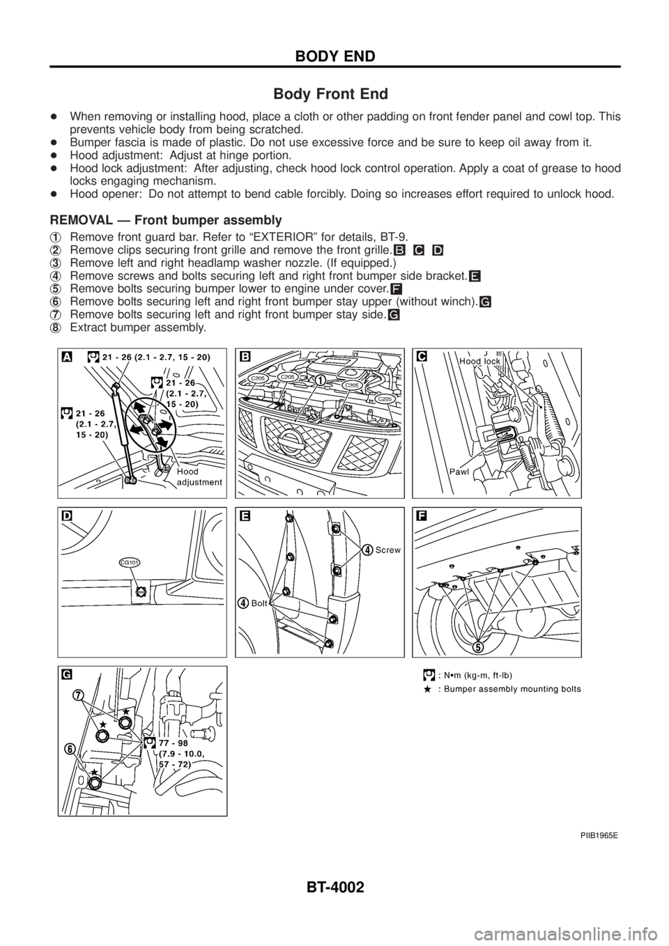
REMOVAL Ð Front bumper assembly
j1Remove front guard bar. Refer to ªEXTERIORº for details, BT-9.
j
2Remove clips securing front grille and remove the front grille.
j3Remove left and right headlamp washer nozzle. (If equipped.)
j
4Remove screws and bolts securing left and right front bumper side bracket.
j5Remove bolts securing bumper lower to engine under cover.
j6Remove bolts securing left and right front bumper stay upper (without winch).
j7Remove bolts securing left and right front bumper stay side.
j8Extract bumper assembly.
PIIB1965E
BODY END
BT-4002
Page 31 of 579

j21License lamp ®nisher
PIIB1973E
EXTERIOR
BT-4011
Page 55 of 579
6 CHECK COMBINATION METER
Refer to EL section.
OK or NG
OKcGO TO 11.
NGcReplace combination meter.
7 CHECK HEADLAMP FUNCTION
1. Start engine.
2. Lighting switch ªONº at 2nd position.
3. Check that headlamp high beams are illuminated.
OK or NG
OKcGO TO 8.
NGcCheck headlamp circuit. Refer to EL section.
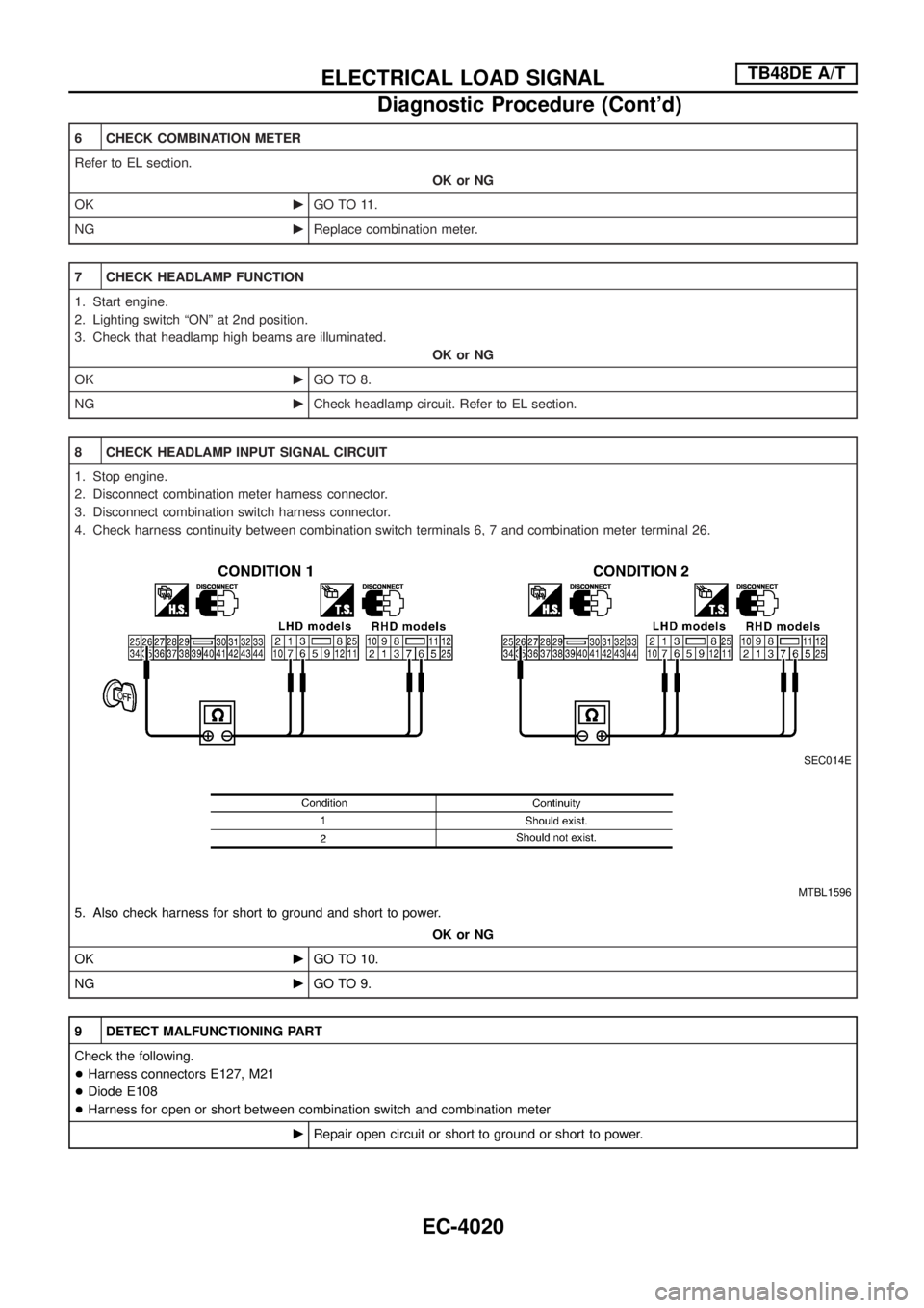
8 CHECK HEADLAMP INPUT SIGNAL CIRCUIT
1. Stop engine.
2. Disconnect combination meter harness connector.
3. Disconnect combination switch harness connector.
4. Check harness continuity between combination switch terminals 6, 7 and combination meter terminal 26.
SEC014E
MTBL1596
5. Also check harness for short to ground and short to power.
OK or NG
OKcGO TO 10.
NGcGO TO 9.
9 DETECT MALFUNCTIONING PART
Check the following.
+Harness connectors E127, M21
+Diode E108
+Harness for open or short between combination switch and combination meter
cRepair open circuit or short to ground or short to power.
ELECTRICAL LOAD SIGNALTB48DE A/T
Diagnostic Procedure (Cont'd)
EC-4020
Page 64 of 579
6 CHECK COMBINATION METER
Refer to EL section.
OK or NG
OKcGO TO 11.
NGcReplace combination meter.
7 CHECK HEADLAMP FUNCTION
1. Start engine.
2. Lighting switch ªONº at 2nd position.
3. Check that headlamp high beams are illuminated.
OK or NG
OKcGO TO 8.
NGcCheck headlamp circuit. Refer to EL section.
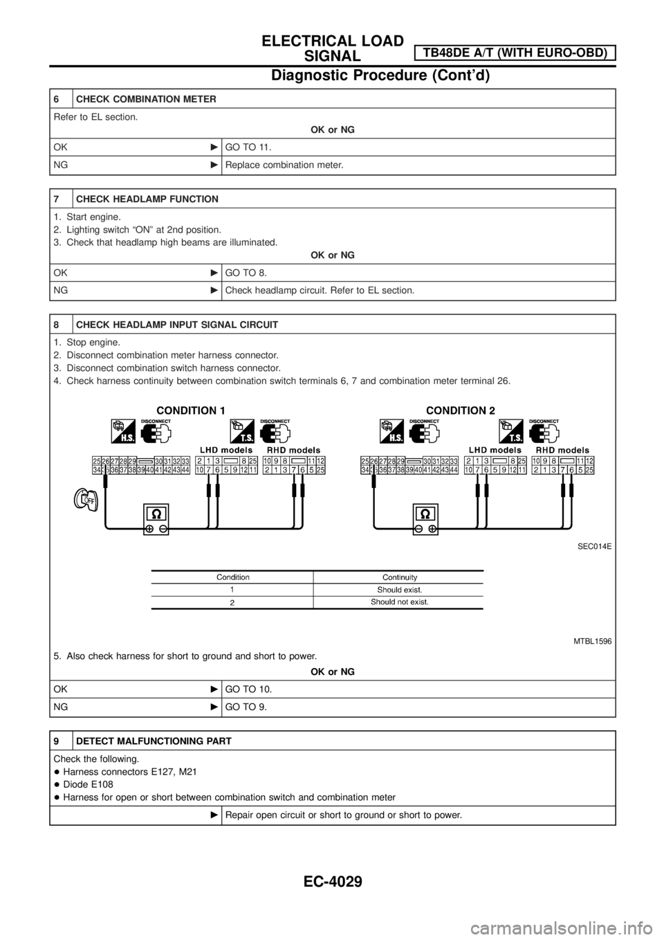
8 CHECK HEADLAMP INPUT SIGNAL CIRCUIT
1. Stop engine.
2. Disconnect combination meter harness connector.
3. Disconnect combination switch harness connector.
4. Check harness continuity between combination switch terminals 6, 7 and combination meter terminal 26.
SEC014E
MTBL1596
5. Also check harness for short to ground and short to power.
OK or NG
OKcGO TO 10.
NGcGO TO 9.
9 DETECT MALFUNCTIONING PART
Check the following.
+Harness connectors E127, M21
+Diode E108
+Harness for open or short between combination switch and combination meter
cRepair open circuit or short to ground or short to power.
ELECTRICAL LOAD
SIGNALTB48DE A/T (WITH EURO-OBD)
Diagnostic Procedure (Cont'd)
EC-4029
Page 76 of 579
TER-
MINAL
NO.WIRE
COLORITEM CONDITIONDATA (DC Voltage and Pulse
Signal)
11 BR/YExhaust gas control
valve control solenoid
valveEngine is running.
Engine speed is below 1,200 rpm
Engine coolant temperature is below 87ÉC
(189ÉF)
Stop the vehicle
Heat up switch is ªONºApproximately 0.1V
Engine is running.
Except the above conditionBATTERY VOLTAGE
(11 - 14V)
14 L Cooling fan relayEngine is running.
Cooling fan is not operatingBATTERY VOLTAGE
(11 - 14V)
Engine is running.
Cooling fan is operatingApproximately 0.1V
15 Y/L Air conditioner relayEngine is running.
Air conditioner switch is ªOFFºBATTERY VOLTAGE
(11 - 14V)
Engine is running.
Both air conditioner switch and blower fan
switch are ªONº
(Compressor is operating)Approximately 0.1V
16 L/W Glow lampIgnition switch ªONº
Glow lamp is ªONºApproximately 1V
Ignition switch ªONº
Glow lamp is ªOFFºBATTERY VOLTAGE
(11 - 14V)
17 G/Y Stop lamp switchIgnition switch ªONº
Brake pedal fully releasedApproximately 0V
Ignition switch ªONº
Brake pedal depressedBATTERY VOLTAGE
(11 - 14V)
18 GMalfunction indicator
lampIgnition switch ªONº
Approximately 1V
Engine is running.
Idle speedBATTERY VOLTAGE
(11 - 14V)
19 LG/REngine coolant tempera-
ture sensorEngine is running.
Approximately 0 - 4.8V
Output voltage varies with
engine coolant temperature
20 R/W Start signalIgnition switch ªONº
Approximately 0V
Ignition switch ªSTARTº
BATTERY VOLTAGE
(11 - 14V)
TROUBLE DIAGNOSIS Ð GENERAL DESCRIPTIONZD30DDTi
ECM Terminals and Reference Value (Cont'd)
EC-4041
Page 92 of 579
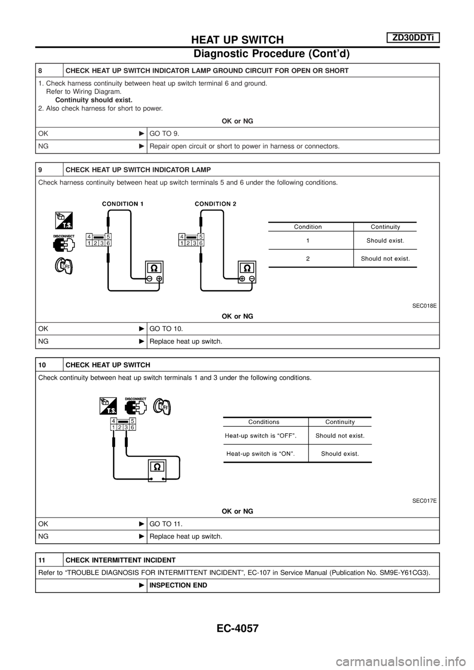
8 CHECK HEAT UP SWITCH INDICATOR LAMP GROUND CIRCUIT FOR OPEN OR SHORT
1. Check harness continuity between heat up switch terminal 6 and ground.
Refer to Wiring Diagram.
Continuity should exist.
2. Also check harness for short to power.
OK or NG
OKcGO TO 9.
NGcRepair open circuit or short to power in harness or connectors.
9 CHECK HEAT UP SWITCH INDICATOR LAMP
Check harness continuity between heat up switch terminals 5 and 6 under the following conditions.
SEC018E
OK or NG
OKcGO TO 10.
NGcReplace heat up switch.
10 CHECK HEAT UP SWITCH
Check continuity between heat up switch terminals 1 and 3 under the following conditions.
SEC017E
OK or NG
OKcGO TO 11.
NGcReplace heat up switch.
11 CHECK INTERMITTENT INCIDENT
Refer to ªTROUBLE DIAGNOSIS FOR INTERMITTENT INCIDENTº, EC-107 in Service Manual (Publication No. SM9E-Y61CG3).
cINSPECTION END
HEAT UP SWITCHZD30DDTi
Diagnostic Procedure (Cont'd)
EC-4057
Page 96 of 579
SECTION
EL
When you read wiring diagrams:
+ Read GI section, ªHOW TO READ WIRING DIAGRAMSº.
When you perform trouble diagnoses, read GI section, ªHOW TO FOLLOW FLOW
CHART IN TROUBLE DIAGNOSESº and ªHOW TO PERFORM EFFICIENT DIAGNOSIS
FOR AN ELECTRICAL INCIDENTº.
+ Check for any service bulletins before servicing the vehicle.
MODIFICATION NOTICE:
+ Wiring Diagrams have been changed.
CONTENTS
POWER SUPPLY ROUTING/WAGON AND
HARDTOP MODELS .................................................4005
Schematic ..............................................................4005
Wiring Diagram Ð POWER Ð..............................4006
GROUND DISTRIBUTION/WAGON AND
HARDTOP MODELS .................................................4016
Main Harness/LHD Models....................................4016
Main Harness/RHD Models ...................................4019
Engine Room Harness/LHD Models .....................4022
Engine Room Harness/RHD Models .....................4024
Body Harness/LHD Models ...................................4026
Body Harness/RHD Models...................................4028
Body No. 2 Harness/LHD Models .........................4030
Body No. 2 Harness/RHD Models.........................4031
Back Door and Rear Window Defogger Harness/
LHD Models ...........................................................4032
Back Door and Rear Window Defogger Harness/
RHD Models ..........................................................4033
COMBINATION SWITCH ...........................................4034
Check .....................................................................4034
STEERING SWITCH ..................................................4036
Check/RHD Models for Europe and LHD Models.4036
Check/RHD Models Except for Europe .................4038
HEADLAMP/WAGON AND HARDTOP MODELS
Ð Conventional Type Ð ..........................................4040
Wiring Diagram Ð H/LAMP Ð ..............................4040
HEADLAMP/WAGON AND HARDTOP MODELS
Ð Xenon Type Ð ......................................................4041
Bulb Replacement .................................................4041
Wiring Diagram Ð H/LAMP Ð ..............................4042 HEADLAMP/WAGON AND HARDTOP MODELS
Ð Headlamp Aiming Control Ð
.............................4044
Wiring Diagram Ð H/AIM Ð/Except for the
Middle East ............................................................4044
HEADLAMP/WAGON AND HARDTOP MODELS
Ð Daytime Light System Ð ....................................4047
Wiring Diagram Ð DTRL Ð ..................................4047
PARKING, LICENSE AND TAIL LAMPS/WAGON
AND HARDTOP MODELS ........................................4049
Wiring Diagram Ð TAIL/L Ð/Type A .....................4049
Wiring Diagram Ð TAIL/L Ð/Type B.....................4051
Wiring Diagram Ð TAIL/L Ð/Type C ....................4053
BACK-UP LAMP/WAGON AND HARDTOP
MODELS ....................................................................4055
Wiring Diagram Ð BACK/L Ð/LHD Models
Except TB48 Engine with A/T................................4055
Wiring Diagram Ð BACK/L Ð/LHD Models for
TB48 Engine with A/T ............................................4056
Wiring Diagram Ð BACK/L Ð/RHD Models
Except TB48 Engine with A/T................................4057
Wiring Diagram Ð BACK/L Ð/RHD Models
for TB48 Engine with A/T ......................................4058
STOP LAMP/WAGON AND HARDTOP MODELS ...4059
Wiring Diagram Ð STOP/L Ð/Type A ..................4059
Wiring Diagram Ð STOP/L Ð/Type B ..................4060
FRONT FOG LAMP/WAGON AND HARDTOP
MODELS ....................................................................4061
Wiring Diagram Ð F/FOG Ð/Except for Europe
and China ..............................................................4061
EL-4001