Page 136 of 579
Bulb Replacement
CAUTION:
+After replacing a new xenon bulb, be sure to make aiming
adjustments.
+ Hold only the plastic base when handling the bulb. Never
touch the glass envelope.
+ Do not leave headlamp re¯ector without bulb for a long
period of time. Dust, moisture, smoke, etc. entering head-
lamp body may affect the performance of the headlamp.
Remove headlamp bulb from the headlamp re¯ector just
before a replacement bulb is installed.
1. Disconnect negative battery cable.
2. Remove side combination lamp and radiator grille.
3. Disconnect headlamp connector.
4. Remove headlamp assembly.
WARNING:
Never service a xenon headlamp with wet hands.
XENON BULB (HIGH AND LOW BEAM)
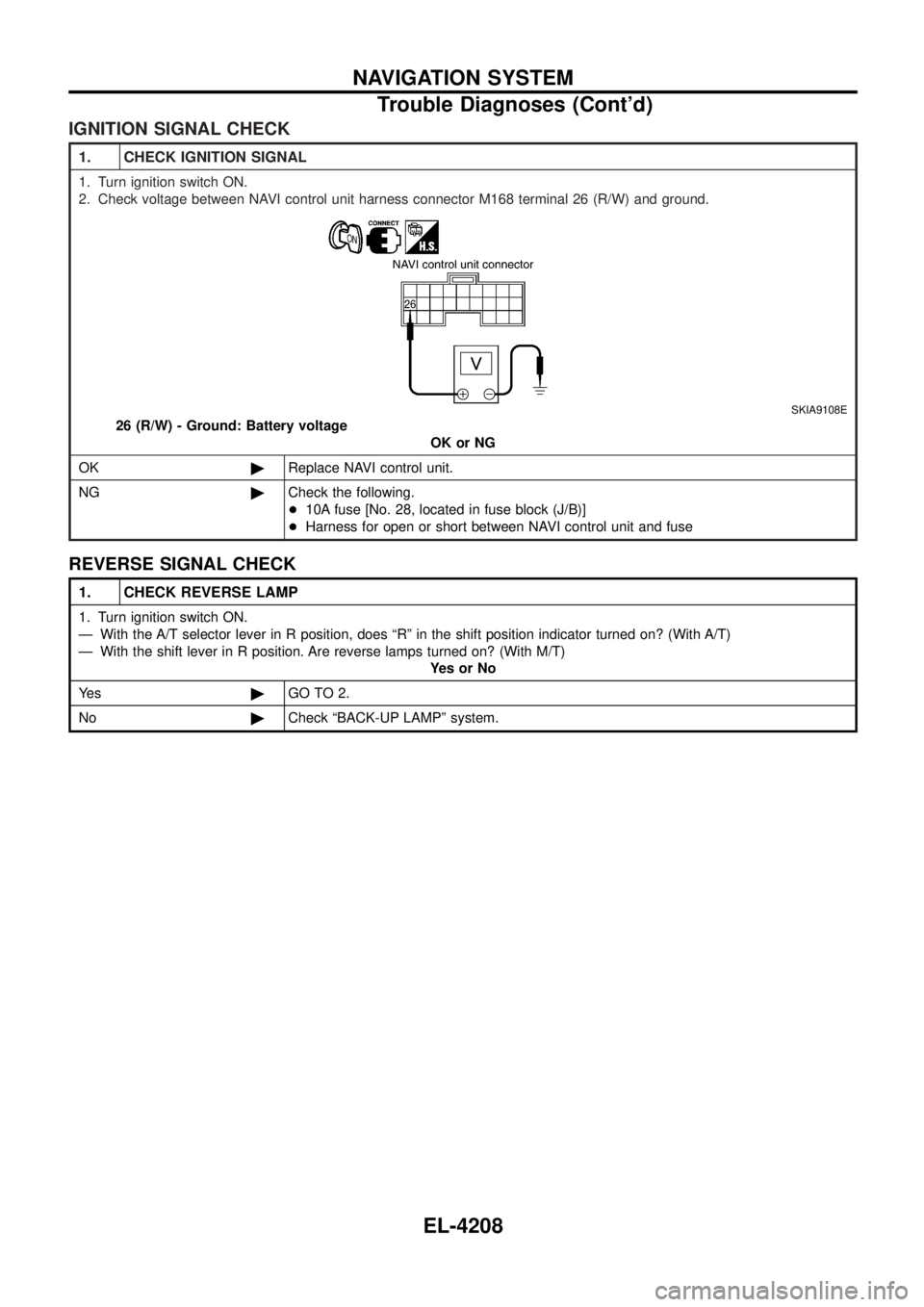
1. Remove headlamp seal cover by turning it counterclockwise.
2. Turn bulb socket counterclockwise with keep pushing, then remove it.
3. Release retaining pin.
4. Remove the xenon bulb.
5. Install in the reverse order of removal.
CAUTION:
+ When disposing of the xenon bulb, do not break it; always
dispose of it as is.
+ Make sure to install the bulb securely; if the xenon bulb is
improperly installed in its socket, high-tension current
leaks occur. This may lead to a melted bulb and/or bulb
socket.
CEL586M
SEL442V
SEL378Y
HEADLAMP/WAGON AND HARDTOP MODELS Ð Xenon Type Ð
EL-4041
Page 303 of 579
IGNITION SIGNAL CHECK
1. CHECK IGNITION SIGNAL
1. Turn ignition switch ON.
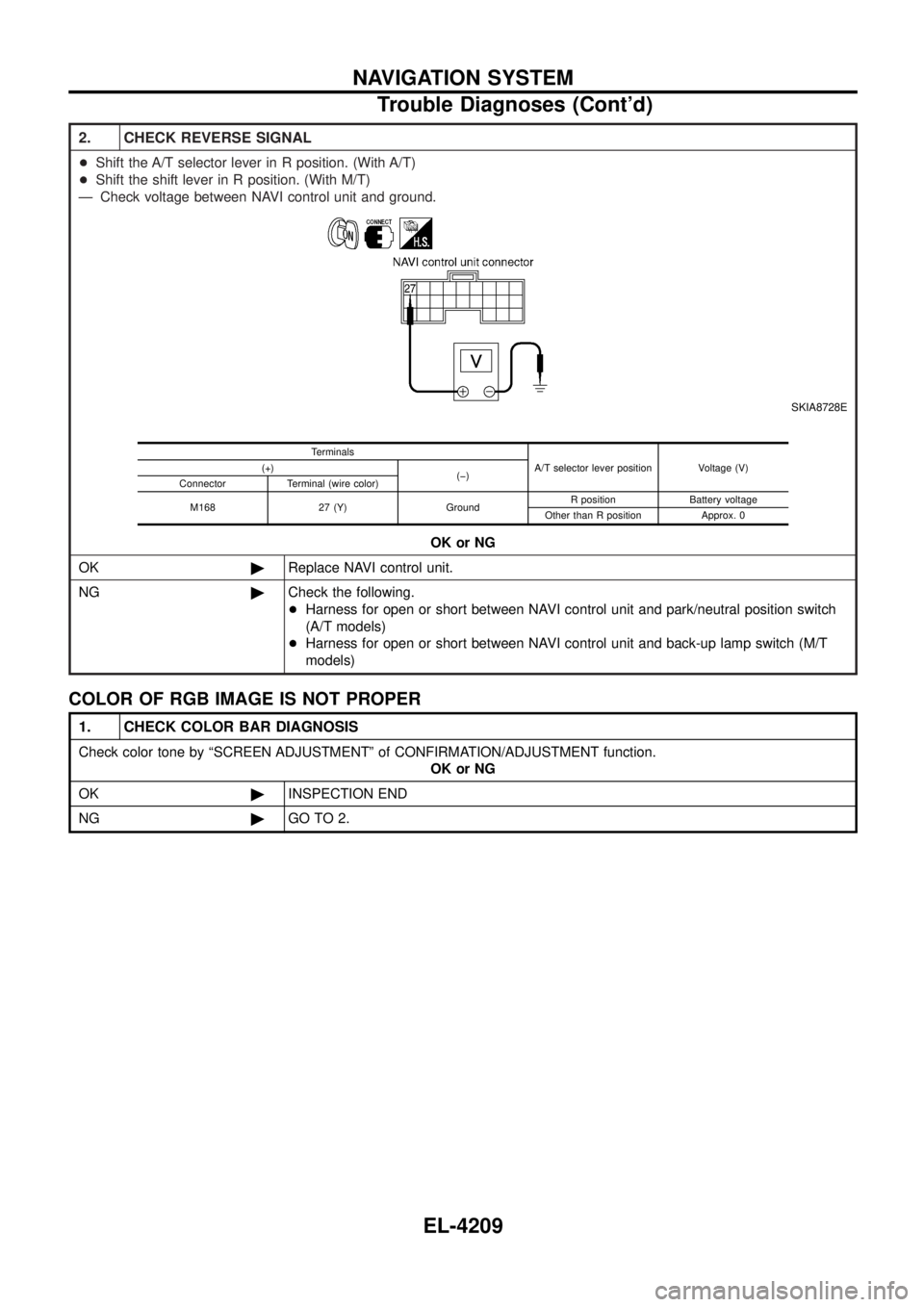
2. Check voltage between NAVI control unit harness connector M168 terminal 26 (R/W) and ground.
SKIA9108E
26 (R/W) - Ground: Battery voltageOK or NG
OK ©Replace NAVI control unit.
NG ©Check the following.
+10A fuse [No. 28, located in fuse block (J/B)]
+ Harness for open or short between NAVI control unit and fuse
REVERSE SIGNAL CHECK
1. CHECK REVERSE LAMP
1. Turn ignition switch ON.
Ð With the A/T selector lever in R position, does ªRº in the shift position indicator turned on? (With A/T)
Ð With the shift lever in R position. Are reverse lamps turned on? (With M/T)
YesorNo
Ye s ©GO TO 2.
No ©Check ªBACK-UP LAMPº system.
NAVIGATION SYSTEM
Trouble Diagnoses (Cont'd)
EL-4208
Page 304 of 579
2. CHECK REVERSE SIGNAL
+Shift the A/T selector lever in R position. (With A/T)
+ Shift the shift lever in R position. (With M/T)
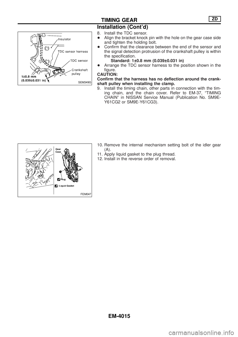
Ð Check voltage between NAVI control unit and ground.
SKIA8728E
OK or NG
OK ©Replace NAVI control unit.
NG ©Check the following.
+Harness for open or short between NAVI control unit and park/neutral position switch
(A/T models)
+ Harness for open or short between NAVI control unit and back-up lamp switch (M/T
models)
Terminals
A/T selector lever position Voltage (V)
(+)
(þ)
Connector Terminal (wire color)
M168 27 (Y) Ground R position Battery voltage
Other than R position Approx. 0
COLOR OF RGB IMAGE IS NOT PROPER
1. CHECK COLOR BAR DIAGNOSIS
Check color tone by ªSCREEN ADJUSTMENTº of CONFIRMATION/ADJUSTMENT function. OK or NG
OK ©INSPECTION END
NG ©GO TO 2.
NAVIGATION SYSTEM
Trouble Diagnoses (Cont'd)
EL-4209
Page 457 of 579
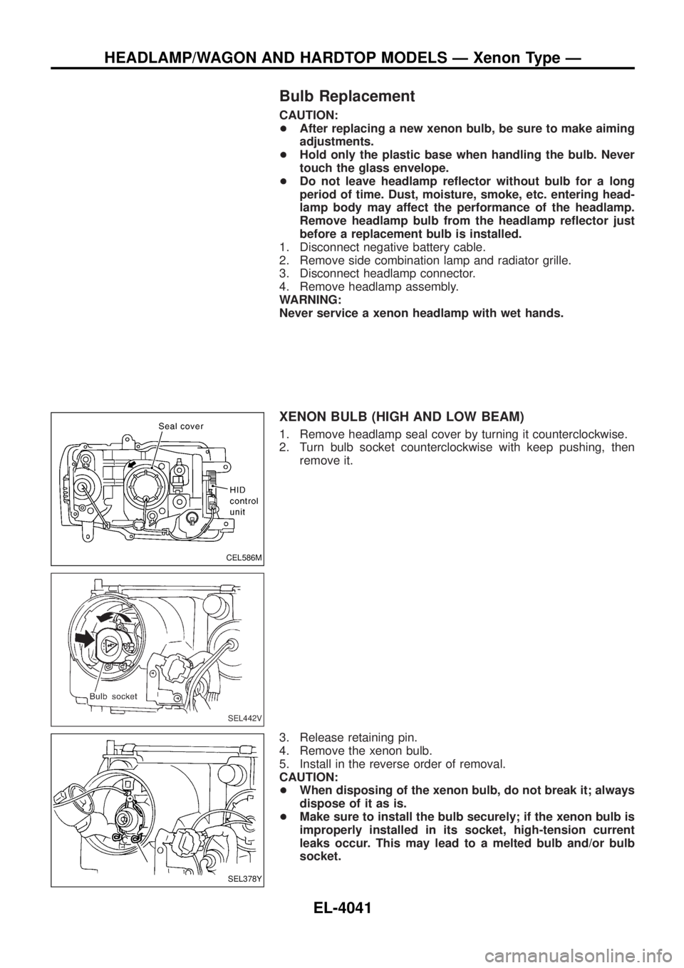
8. Install the TDC sensor.
+Align the bracket knock pin with the hole on the gear case side
and tighten the holding bolt.
+Con®rm that the clearance between the end of the sensor and
the signal detection protrusion of the crankshaft pulley is within
the speci®cation.
Standard: 1 0.8 mm (0.039 0.031 in)
+Arrange the TDC sensor harness to the position shown in the
®gure.
CAUTION:
Con®rm that the harness has no de¯ection around the crank-
shaft pulley when installing the clamp.
9. Install the timing chain, other parts in connection with the tim-
ing chain, and the chain cover. Refer to EM-37, ªTIMING
CHAINº in NISSAN Service Manual (Publication No. SM9E-
Y61CG2 or SM9E-Y61CG3).
10. Remove the internal mechanism setting bolt of the idler gear
(A).
11. Apply liquid gasket to the plug thread.
12. Install in the reverse order of removal.
SEM349G
FEM047
TIMING GEARZD
Installation (Cont'd)
EM-4015