2004 NISSAN MAXIMA spare tire location
[x] Cancel search: spare tire locationPage 181 of 280

ing abruptly or when braking on a slippery road.
Thus, difficult steering and swerving of the ve-
hicle due to locked wheels is minimized. The
system detects the wheel rotation rate and elec-
tronically controls the pressure applied to each
brake. Slight vibration on the brake pedal accom-
panied by noise usually occurs while the ABS
system is operating. Such vibration and noise
encountered during abrupt braking is not a prob-
lem, but indicates that the system is functioning
properly. However, the pulsation may indicate
that road conditions are hazardous and extra care
is required while driving.
Self-test feature
The anti-lock brake system consists of electronic
sensors and hydraulic solenoids controlled by a
computer. The computer has a built-in diagnostic
feature that tests the system each time you start
the engine and move the vehicle at a low speed in
forward or reverse. When the self-test occurs,
you may hear a ‘‘clunk’’ noise and/or feel a pulsa-
tion in the brake pedal. This is normal and is not
an indication of any malfunction. If the computer
senses any malfunction, it switches the anti-lock
brake system off and turns on the ABS brake
warning light on the instrument panel. The brake
system then operates normally, but without anti-
lock assistance.If a malfunction occurs in the system, the anti-
lock function will not operate, but the standard
vehicle brake system will continue to operate
normally. The ABS brake warning light will then
come on.
If the light comes on during the self-test or while
driving, take the vehicle to a NISSAN dealer for
repair.
WARNING
cThe anti-lock brake system is a sophis-
ticated device, but it cannot prevent ac-
cidents resulting from careless or dan-
gerous driving techniques. It can help
maintain vehicle control during braking
on slippery surfaces, but remember that
the stopping distance on slippery sur-
faces will be longer than on normal
surfaces even with the anti-lock brake
system. Stopping distances may also
be longer on rough, gravel or snow cov-
ered roads, or if you are using tire
chains. Tire type and condition may also
affect braking effectiveness. Always
maintain a safe distance from the ve-
hicle in front of you. Ultimately, the re-
sponsibility for safety of self and others
rests in the hands of the driver.cTire type and condition of tires may also
affect braking effectiveness.
cWhen replacing tires, install the speci-
fied size of tires on all four wheels.
cWhen installing a spare tire, make sure
it is the proper size and type as speci-
fied on the tire placard. For tire placard
location information, refer to “Tire plac-
ard” in the “Technical and consumer
information” section of this manual.
cRefer to “Wheels and tires” in the
“Maintenance and do-it-yourself” sec-
tion of this manual.
Starting and driving5-19
ZREVIEW COPY:Ð2004 Maxima(max)
Owners Manual(owners)ÐUSA English(nna)
10/07/03Ðtbrooks
X
Page 245 of 280

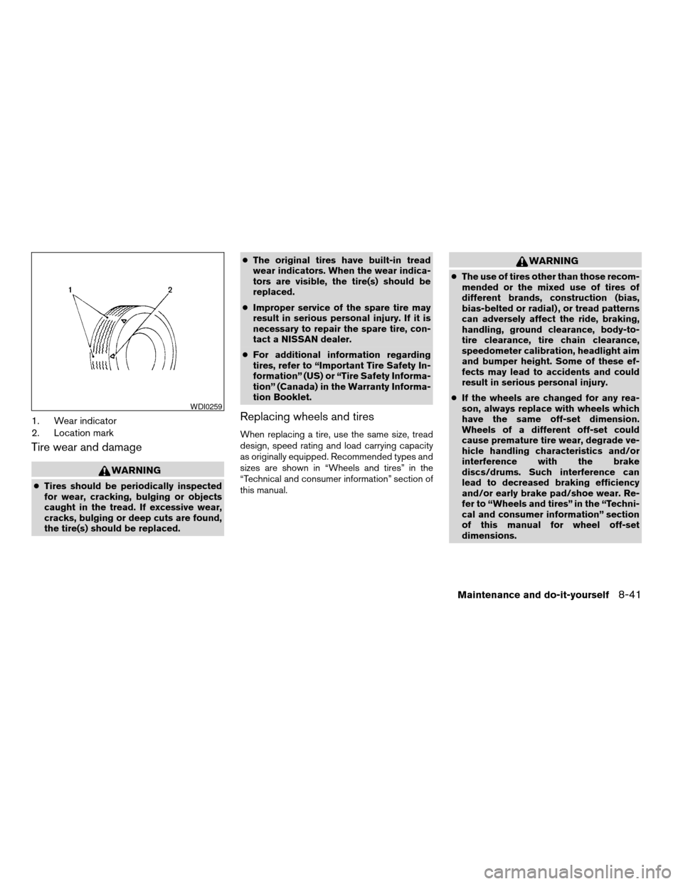
1. Wear indicator
2. Location mark
Tire wear and damage
WARNING
cTires should be periodically inspected
for wear, cracking, bulging or objects
caught in the tread. If excessive wear,
cracks, bulging or deep cuts are found,
the tire(s) should be replaced.cThe original tires have built-in tread
wear indicators. When the wear indica-
tors are visible, the tire(s) should be
replaced.
cImproper service of the spare tire may
result in serious personal injury. If it is
necessary to repair the spare tire, con-
tact a NISSAN dealer.
cFor additional information regarding
tires, refer to “Important Tire Safety In-
formation” (US) or “Tire Safety Informa-
tion” (Canada) in the Warranty Informa-
tion Booklet.
Replacing wheels and tires
When replacing a tire, use the same size, tread
design, speed rating and load carrying capacity
as originally equipped. Recommended types and
sizes are shown in “Wheels and tires” in the
“Technical and consumer information” section of
this manual.
WARNING
cThe use of tires other than those recom-
mended or the mixed use of tires of
different brands, construction (bias,
bias-belted or radial) , or tread patterns
can adversely affect the ride, braking,
handling, ground clearance, body-to-
tire clearance, tire chain clearance,
speedometer calibration, headlight aim
and bumper height. Some of these ef-
fects may lead to accidents and could
result in serious personal injury.
cIf the wheels are changed for any rea-
son, always replace with wheels which
have the same off-set dimension.
Wheels of a different off-set could
cause premature tire wear, degrade ve-
hicle handling characteristics and/or
interference with the brake
discs/drums. Such interference can
lead to decreased braking efficiency
and/or early brake pad/shoe wear. Re-
fer to “Wheels and tires” in the “Techni-
cal and consumer information” section
of this manual for wheel off-set
dimensions.
WDI0259
Maintenance and do-it-yourself8-41
ZREVIEW COPY:Ð2004 Maxima(max)
Owners Manual(owners)ÐUSA English(nna)
10/20/03Ðarosenma
X
Page 260 of 280

Use the following steps to mount the front license
plate:
Before mounting the license plate, confirm that
the following parts are enclosed in the plastic
bag:
cLicense plate bracket
cLicense plate bracket screws x 2
cLicense plate screws x 2
cScrew grommets x 2
1. Make a shallow hole in the bumper fascia at
the location marks (small dimples) using a
0.39 in (10 mm) drill. To avoid damaging the
area behind the fascia, apply only light pres-
sure to the drill.
2. Insert the grommets into the holes in the
bumper fascia.
3. Insert a small flat-bladed screwdriver into
the grommet hole to turn the threaded part of
the grommet 90°.
4. Mount the license plate bracket using the
two longer screws.
5. Use the two shorter hex head screws to
mount the license plate to the license plate
bracket.WARNING
cIt is extremely dangerous to ride in a
cargo area inside a vehicle. In a colli-
sion, people riding in these areas are
more likely to be seriously injured or
killed.
cDo not allow people to ride in any area
of your vehicle that is not equipped with
seats and seat belts.
cBe sure everyone in your vehicle is in a
seat and using a seat belt properly.
TERMS
It is important to familiarize yourself with the fol-
lowing terms before loading your vehicle:
cCurb Weight (actual weight of your vehicle)
- vehicle weight including: standard and op-
tional equipment, fluids, emergency tools,
and spare tire assembly. This weightdoes
notinclude passengers and cargo.
cGVW (Gross Vehicle Weight) - curb weight
plus the combined weight of passengers
and cargo.
cGVWR (Gross Vehicle Weight Rating) -
maximum total weight (load) limit specified
for the vehicle.cGAWR (Gross Axle Weight Rating) - maxi-
mum weight (load) limit specified for the
front or rear axle.
DETERMINING VEHICLE LOAD
CAPACITY
The load capacity of this vehicle is determined by
weight, not by available cargo space. For ex-
ample, a luggage rack, bike carrier, cartop carrier
or similar equipment does not increase load car-
rying capacity of your vehicle.
To determine vehicle load capacity:
Vehicle weight can be determined by using a
commercial-grade scale, found at places such as
a truck stop, gravel quarry, grain elevator, or a
scrap metal recycling facility.
1. Determine the curb weight of your vehicle.
2. Compare the curb weight amount to the
GVWR specified for your vehicle to deter-
mine how much more weight your vehicle
can carry.
VEHICLE LOADING INFORMATION
9-12Technical and consumer information
ZREVIEW COPY:Ð2004 Maxima(max)
Owners Manual(owners)ÐUSA English(nna)
10/20/03Ðarosenma
X