2004 NISSAN MAXIMA fuse
[x] Cancel search: fusePage 14 of 280
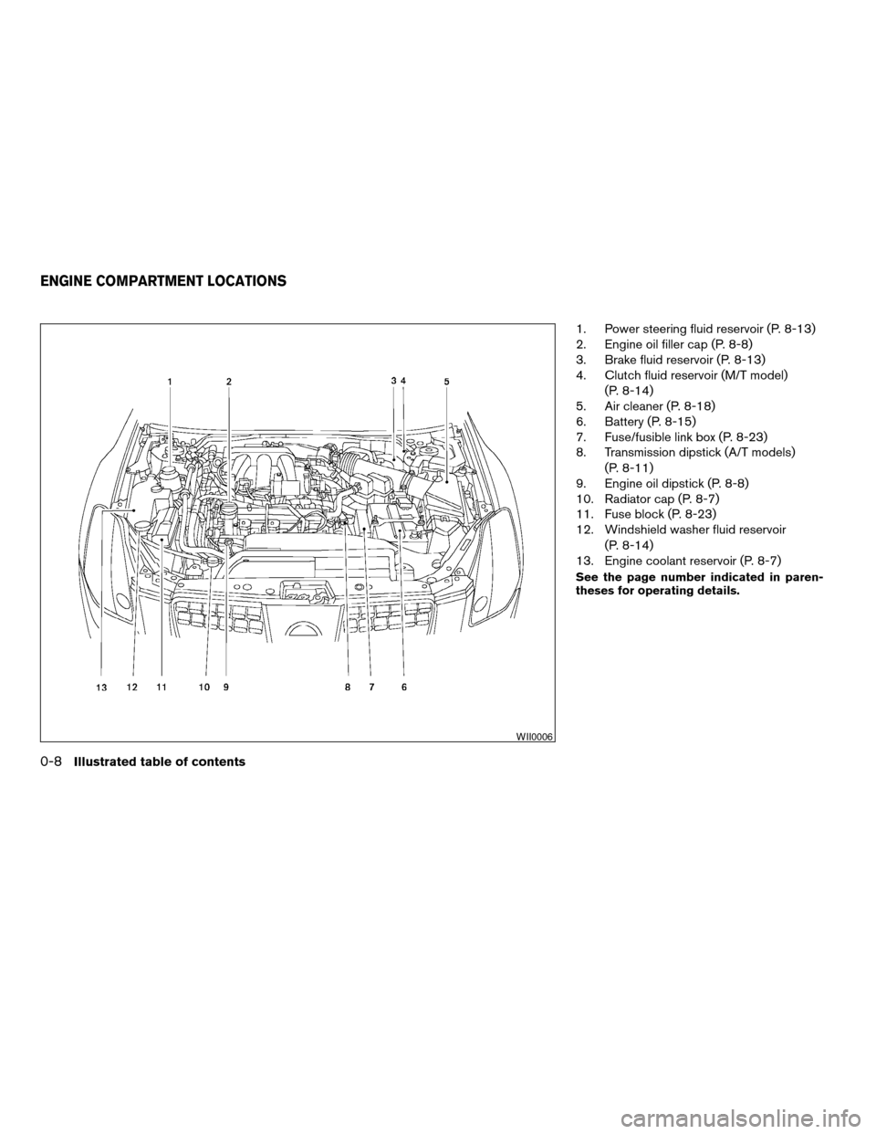
1. Power steering fluid reservoir (P. 8-13)
2. Engine oil filler cap (P. 8-8)
3. Brake fluid reservoir (P. 8-13)
4. Clutch fluid reservoir (M/T model)
(P. 8-14)
5. Air cleaner (P. 8-18)
6. Battery (P. 8-15)
7. Fuse/fusible link box (P. 8-23)
8. Transmission dipstick (A/T models)
(P. 8-11)
9. Engine oil dipstick (P. 8-8)
10. Radiator cap (P. 8-7)
11. Fuse block (P. 8-23)
12. Windshield washer fluid reservoir
(P. 8-14)
13. Engine coolant reservoir (P. 8-7)
See the page number indicated in paren-
theses for operating details.
WII0006
ENGINE COMPARTMENT LOCATIONS
0-8Illustrated table of contents
ZREVIEW COPY:Ð2004 Maxima(max)
Owners Manual(owners)ÐUSA English(nna)
10/20/03Ðskoniecz
X
Page 88 of 280
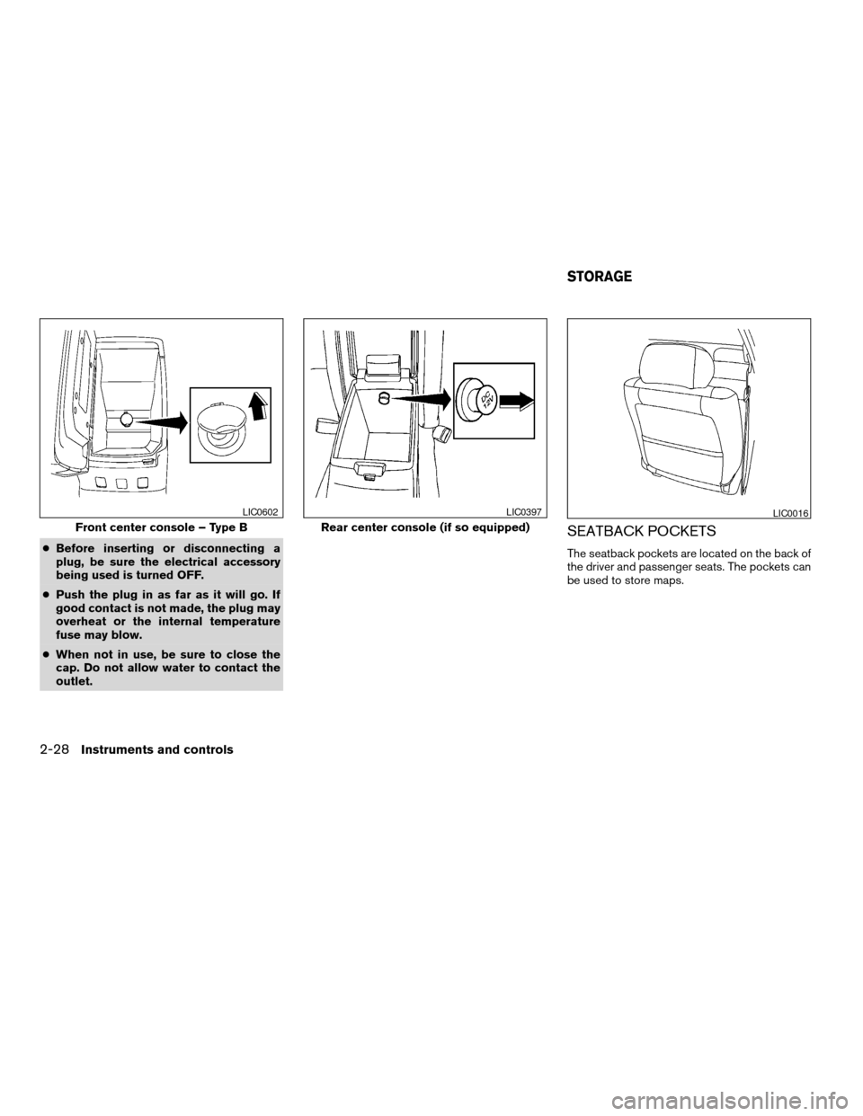
cBefore inserting or disconnecting a
plug, be sure the electrical accessory
being used is turned OFF.
cPush the plug in as far as it will go. If
good contact is not made, the plug may
overheat or the internal temperature
fuse may blow.
cWhen not in use, be sure to close the
cap. Do not allow water to contact the
outlet.
SEATBACK POCKETS
The seatback pockets are located on the back of
the driver and passenger seats. The pockets can
be used to store maps.
Front center console – Type B
LIC0602
Rear center console (if so equipped)
LIC0397LIC0016
STORAGE
2-28Instruments and controls
ZREVIEW COPY:Ð2004 Maxima(max)
Owners Manual(owners)ÐUSA English(nna)
10/07/03Ðtbrooks
X
Page 126 of 280
3. Adjust the driver’s seat, steering column and
outside mirrors to the desired positions by
manually operating each adjusting switch.
For additional information, see “Seats” in the
“Safety—Seats, seat belts and supplemen-
tal air bags” section and “Steering wheel”
and “Outside mirrors” earlier in this section.
During this step, do not turn the ignition to
any positions other than ON.
4. Push the SET switch and, within 5 seconds,
push the memory switch (1 or 2) fully for at
least 1 second.
The indicator light for the pushed memory
switch will come on and stay on for approxi-
mately 5 seconds after pushing the switch.
After the indicator light goes off, the se-
lected positions are stored in the selected
memory (1 or 2) .
If memory is stored in the same memory switch,
the previous memory will be deleted.
Linking a keyfob to a stored memory
position
A keyfob can be linked to a stored memory posi-
tion with the following procedure.
1. Follow the steps for storing a memory posi-
tion.2. While the indicator light for the memory
switch being set is illuminated for 5 sec-
onds, press the
button on the keyfob.
The indicator light will blink. After the indica-
tor light goes off, the keyfob is linked to that
memory setting.
With the key removed from the ignition switch,
press the
button on the keyfob. The driv-
er’s seat and outside mirrors will move to the
memorized position.
Confirming memory storage
cTurn the ignition ON and push the SET
switch. If the main memory has not been
stored, the indicator light will come on for
approximately 0.5 seconds. When the
memory has stored the position, the indica-
tor light will stay on for approximately 5 sec-
onds.
cIf the battery cable is disconnected, or if the
fuse blows, the memory will be canceled. In
such a case, reset the desired positions
using the following procedures.
1. Open and close the driver’s door more than
two times with the ignition key in the LOCK
position.
2. Reset the desired position using the previ-
ous procedure.
Selecting the memorized position
1. Set the automatic transmission selector le-
ver to the P (Park) position.
2. Turn the ignition ON.
3. Push the memory switch (1 or 2) fully for at
least 1 second.
The driver’s seat, steering column and out-
side mirrors will move to the memorized po-
sition with the indicator light flashing, and
then the light will stay on for approximately 5
seconds.
ENTRY/EXIT FUNCTION (for
automatic transmission model)
This system is designed so that the driver’s seat
and steering column will automatically move
when the automatic transmission selector lever is
in the P (Park) position. This allows the driver to
get into and out of the driver’s seat more easily.
(This feature is not available on manual transmis-
sion model.)
The driver’s seat will slide backward and the
steering wheel will move up:
cWhen the key is removed from the ignition
switch.
cWhen the driver’s door is opened with the
key turned to LOCK.
3-20Pre-driving checks and adjustments
ZREVIEW COPY:Ð2004 Maxima(max)
Owners Manual(owners)ÐUSA English(nna)
10/20/03Ðarosenma
X
Page 153 of 280
To release the mute or pause, push the button
again.
FM/AM/SAT radio operation
FM/AM/SAT radio select:
Pushing the FM-AM or SAT radio select button
will change the band as follows:
AMÃ!FM or SAT (Satellite)
When FM-AM or SAT radio select button is
pushed while the ignition switch is in the ACC or
ON, the radio will come on at the station last
played.
The last station played will also come on when
the ON·OFF/Volume control knob is depressed
to ON.
No satellite radio reception is available and “NO
SAT” is displayed when the SAT button is
pressed unless optional satellite receiver and
antenna are installed (late availability only/retrofit
unavailable without factory satellite radio pre-
wiring) , and an XMTor SIRIUS™ satellite radio
service subscription is active.
If a compact disc or tape is playing when the
FM-AM or SAT radio select button is pushed, the
compact disc or tape will automatically be turned
off and the last radio station played will come on.The FM stereo indicator ST will glow during FM
stereo reception. When the stereo broadcast
signal is weak, the radio will automatically change
from stereo to monaural reception.TUNE (Tuning):
WARNING
The radio should not be tuned while driv-
ing so full attention may be given to ve-
hicle operation.
To manually tune the radio, push the TUNE button
(
or) or turn the tuning knob to right
or left.
To move quickly through the channels, hold either
the
orbutton down for more than
1.5 seconds.
SEEK tuning:
Push the SEEK button (
or) for less
than 1.5 seconds to tune from high to low or low
to high frequencies and stop at the next broad-
casting station.
SCAN tuning:
Push the
orbutton for more than
1.5 seconds to stop at each broadcasting station
for 5 seconds. Pushing the button again during
this 5 seconds period will stop SCAN tuning and
the radio will remain tuned to that station. Ifthe
orbutton is not pushed within 5
seconds, SCAN tuning moves to the next station.
Station memory operations:
18 stations can be set for the FM, AM and SAT
radio to the A, B and C preset button.
1. Choose preset channel A, B or C using the
preset select button.
2. Tune to the desired station using manual,
SEEk or SCAN tuning. Push and hold any of
the desired station memory buttons (1 - 6)
until a beep sound is heard. (The radio mutes
when the select button is pushed.)
3. The channel indicator will then come on and
the sound will resume. Memorizing is now
complete.
4.
Other buttons can be set in the same manner.
If the battery cable is disconnected, or if the fuse
blows, the radio memory will be canceled. In that
case, reset the desired stations.
Radio data system (RDS) (if so equipped):
RDS stands for Radio Data System, and is a data
information service transmitted by some radio
stations on the FM band (not AM band) and/or
SAT radio encoded within a regular radio broad-
cast. Currently, most RDS stations are in large
cities, but many stations are now considering
broadcasting RDS data.
Display screen, heater, air conditioner and audio systems4-25
ZREVIEW COPY:Ð2004 Maxima(max)
Owners Manual(owners)ÐUSA English(nna)
10/07/03Ðtbrooks
X
Page 205 of 280
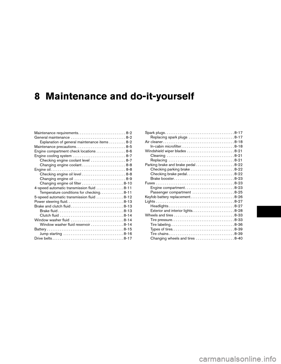
8 Maintenance and do-it-yourself
Maintenance requirements..........................8-2
General maintenance..............................8-2
Explanation of general maintenance items.........8-2
Maintenance precautions...........................8-5
Engine compartment check locations................8-6
Engine cooling system.............................8-7
Checking engine coolant level...................8-7
Changing engine coolant........................8-8
Engine oil.........................................8-8
Checking engine oil level........................8-8
Changing engine oil............................8-9
Changing engine oil filter.......................8-10
4-speed automatic transmission fluid...............8-11
Temperature conditions for checking.............8-11
5-speed automatic transmission fluid...............8-12
Power steering fluid...............................8-13
Brake and clutch fluid.............................8-13
Brake fluid....................................8-13
Clutch fluid...................................8-14
Window washer fluid.............................8-14
Window washer fluid reservoir..................8-14
Battery..........................................8-15
Jump starting.................................8-16
Drive belts.......................................8-17Spark plugs......................................8-17
Replacing spark plugs.........................8-17
Air cleaner.......................................8-18
In-cabin microfilter.............................8-18
Windshield wiper blades..........................8-21
Cleaning.....................................8-21
Replacing....................................8-21
Parking brake and brake pedal.....................8-22
Checking parking brake........................8-22
Checking brake pedal..........................8-22
Brake booster.................................8-23
Fuses...........................................8-23
Engine compartment...........................8-23
Passenger compartment.......................8-25
Keyfob battery replacement........................8-26
Lights...........................................8-27
Headlights....................................8-27
Exterior and interior lights.......................8-28
Wheels and tires.................................8-33
Tire pressure..................................8-33
Tire labeling...................................8-36
Types of tires..................................8-39
Tire chains....................................8-39
Changing wheels and tires.....................8-40
ZREVIEW COPY:Ð2004 Maxima(max)
Owners Manual(owners)ÐUSA English(nna)
10/20/03Ðarosenma
X
Page 210 of 280
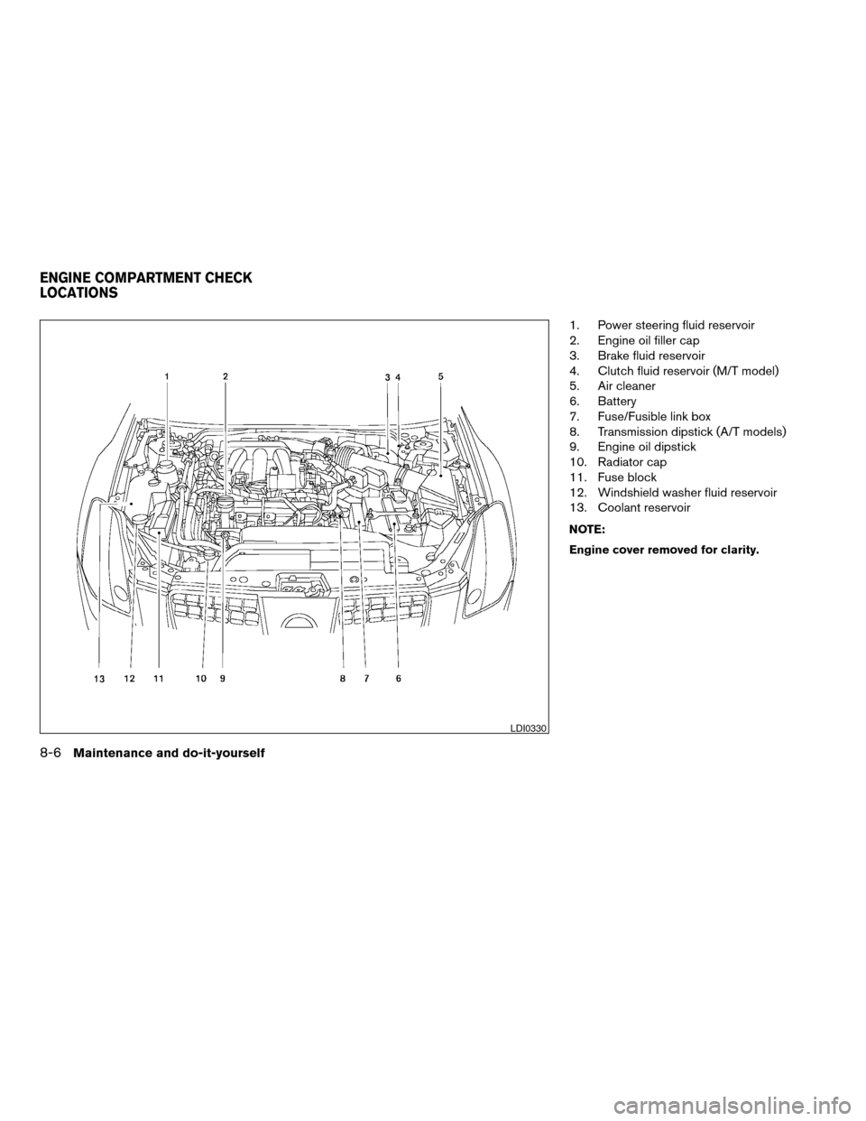
1. Power steering fluid reservoir
2. Engine oil filler cap
3. Brake fluid reservoir
4. Clutch fluid reservoir (M/T model)
5. Air cleaner
6. Battery
7. Fuse/Fusible link box
8. Transmission dipstick (A/T models)
9. Engine oil dipstick
10. Radiator cap
11. Fuse block
12. Windshield washer fluid reservoir
13. Coolant reservoir
NOTE:
Engine cover removed for clarity.
LDI0330
ENGINE COMPARTMENT CHECK
LOCATIONS
8-6Maintenance and do-it-yourself
ZREVIEW COPY:Ð2004 Maxima(max)
Owners Manual(owners)ÐUSA English(nna)
10/20/03Ðarosenma
X
Page 227 of 280
Self-adjusting brakes
Your vehicle is equipped with self-adjusting
brakes.
The front and rear disc-type brakes self-adjust
every time the brake pedal is applied.
WARNING
See a NISSAN dealer for a brake system
check if the brake pedal height does not
return to normal.
Brake pad wear indicators
The disc brake pads on your vehicle have audible
wear indicators. When a brake pad requires re-
placement, a high pitched scraping or screech-
ing sound will be heard when the vehicle is in
motion. The noise will be heard whether or not the
brake pedal is depressed. Have the brakes
checked as soon as possible if the wear indicator
sound is heard.
Under some driving or climate conditions, occa-
sional brake squeak, squeal or other noise may
be heard. Occasional brake noise during light to
moderate stops is normal and does not affect the
function or performance of the brake system.
Proper brake inspection intervals should
be followed.For more information regarding
brake inspections, see the appropriate mainte-nance schedule information in the “NISSAN Ser-
vice and Maintenance Guide”.
BRAKE BOOSTER
Check the brake booster function as follows:
1. With the engine off, press and release the
brake pedal several times. When brake
pedal movement (distance of travel) remains
the same from one pedal application to the
next, continue on to the next step.
2. While depressing the brake pedal, start the
engine. The pedal height should drop a little.
3. With the brake pedal depressed, stop the
engine. Keep the pedal depressed for about
30 seconds. The pedal height should not
change.
4. Run the engine for one minute without de-
pressing the brake pedal, then turn it off.
Depress the brake pedal several times. The
pedal travel distance will decrease gradually
with each depression as the vacuum is re-
leased from the booster.
If the brakes do not operate properly, have the
brakes checked by a NISSAN dealer.
ENGINE COMPARTMENT
CAUTION
Never use a fuse of a higher or lower
amperage rating than specified on the
fuse box cover. This could damage the
electrical system or cause a fire.
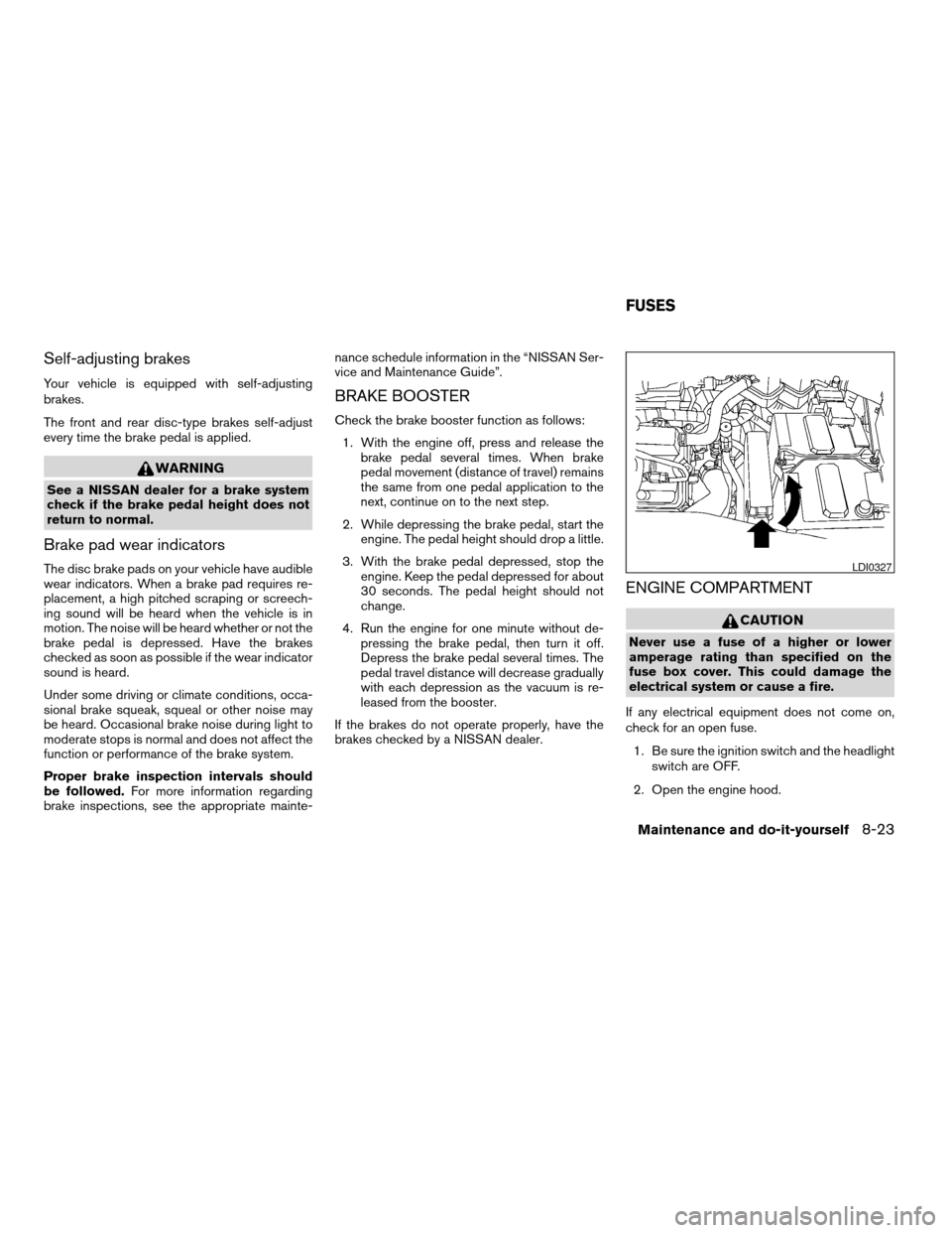
If any electrical equipment does not come on,
check for an open fuse.
1. Be sure the ignition switch and the headlight
switch are OFF.
2. Open the engine hood.
LDI0327
FUSES
Maintenance and do-it-yourself8-23
ZREVIEW COPY:Ð2004 Maxima(max)
Owners Manual(owners)ÐUSA English(nna)
10/20/03Ðarosenma
X
Page 228 of 280
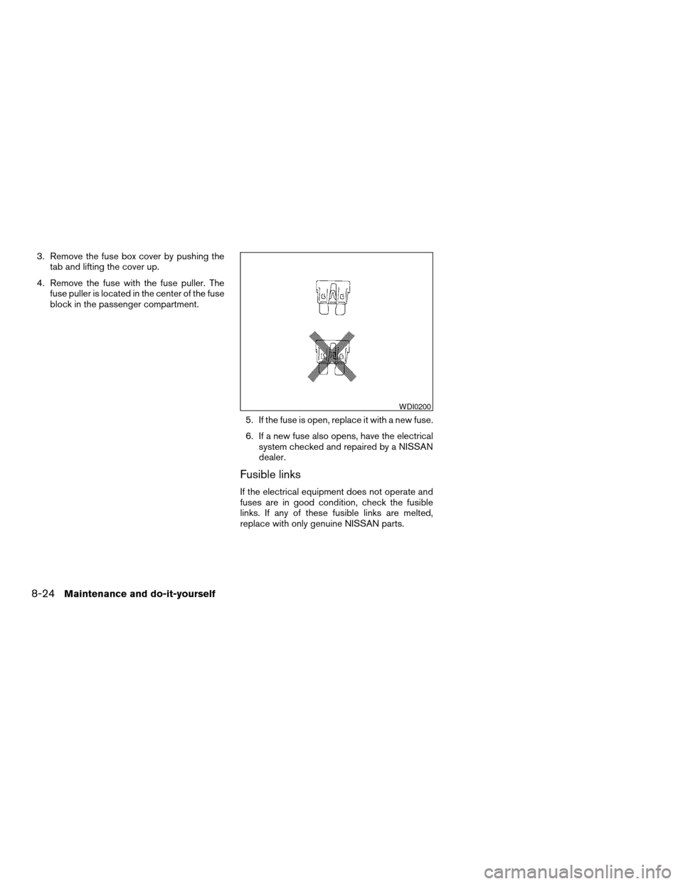
3. Remove the fuse box cover by pushing the
tab and lifting the cover up.
4. Remove the fuse with the fuse puller. The
fuse puller is located in the center of the fuse
block in the passenger compartment.
5. If the fuse is open, replace it with a new fuse.
6. If a new fuse also opens, have the electrical
system checked and repaired by a NISSAN
dealer.
Fusible links
If the electrical equipment does not operate and
fuses are in good condition, check the fusible
links. If any of these fusible links are melted,
replace with only genuine NISSAN parts.
WDI0200
8-24Maintenance and do-it-yourself
ZREVIEW COPY:Ð2004 Maxima(max)
Owners Manual(owners)ÐUSA English(nna)
10/20/03Ðarosenma
X