Page 1300 of 3870
TORQUE SPECIFICATION
S
See illustration in REMOVAL & INSTALLATION
or OVERHAUL
.
WIRING DIAGRAMS For wiring diagrams, see STARTING/CHARGING
.
2004 Mitsubishi Endeavor Limited
2004 STARTING & CHARGING SYSTEMS Generators & Regulators - Endeavor
Page 2521 of 3870

means of a forged key or by connecting the ignition wiring directly. The system is
significantly safe and reliable against theft. In addition, the driver has only to turn
the ignition switch to the "ON" position to activate the immobilizer system. If the
requirements for starting the engine are not satisfied, the engine will be
immobilized. If a registered ignition key is lost, all your ignition keys need to be
registered again using scan tool MB991958 (MUT-III Sub Assembly) to ensure
security (Refer to ON
-VEHICLE SERVICE
). An additional ignition key can be
registered as follows (only if no ignition keys are lost):
Using scan tool MB991958 (MUT-III Sub Assembly) (Refer to ON
-
VEHICLE SERVICE
).
By operating two ignition keys that have been already registered (Refer toON
-
VEHICLE SERVICE
).
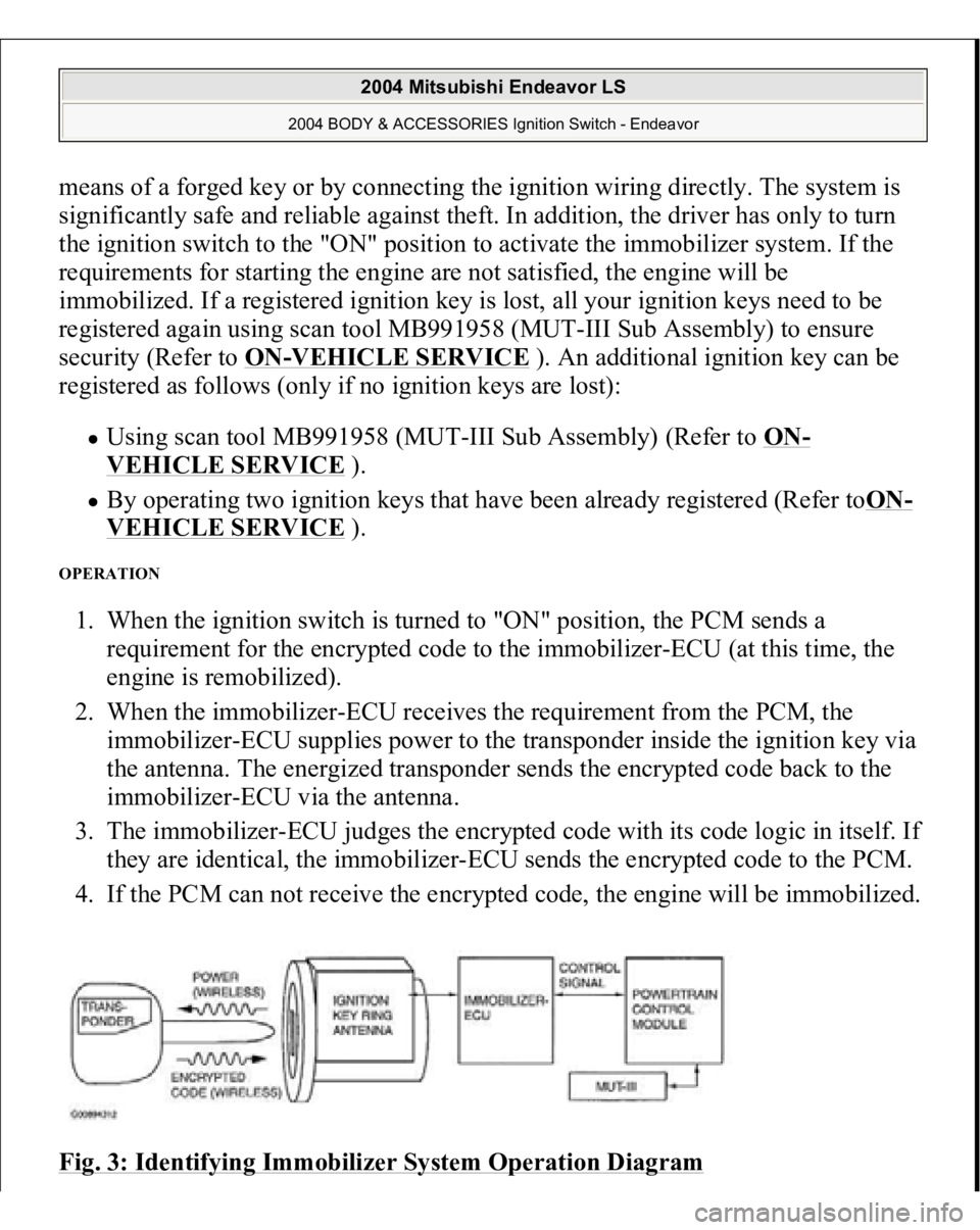
OPERATION 1. When the ignition switch is turned to "ON" position, the PCM sends a
requirement for the encrypted code to the immobilizer-ECU (at this time, the
engine is remobilized).
2. When the immobilizer-ECU receives the requirement from the PCM, the
immobilizer-ECU supplies power to the transponder inside the ignition key via
the antenna. The energized transponder sends the encrypted code back to the
immobilizer-ECU via the antenna.
3. The immobilizer-ECU judges the encrypted code with its code logic in itself. If
they are identical, the immobilizer-ECU sends the encrypted code to the PCM.
4. If the PCM can not receive the encrypted code, the engine will be immobilized.
Fig. 3: Identifying Immobilizer System Operation Diagram
2004 Mitsubishi Endeavor LS
2004 BODY & ACCESSORIES Ignition Switch - Endeavor
Page 3485 of 3870
Fig. 220: G And Yaw Rate Sensor Power Supply Circuit Diagram & Connector Identification
Courtesy of MITSUBISHI MOTOR SALES OF AMERICA.
Fig. 221: Identifying Connectors: C
-214, C
-215
Courtesy of MITSUBISHI MOTOR SALES OF AMERICA.
CIRCUIT OPERATION
The G and yaw rate sensor is energized by the ignition switch (IG2) through
multi-purpose fuse 13 and the G and yaw rate sensor terminal 1. If the power supply to the G and yaw rate sensor has failed, TCL/ASC-ECU
related DTC U1105 is set.
TROUBLESHOOTING HINTS (The most likely causes for this case:)
Damaged wiring harness or connector Defective battery Char
ging sys
tem fail
ed
2004 Mitsubishi Endeavor LS
2004 BRAKES Traction Control, Active Skid Control System - Endeavor
Page 3552 of 3870
TORQUE SPECIFICATIONS TORQUE SPECIFICATIONS WIRING DIAGRAMS For starting system wiring diagram see STARTING/CHARGING in appropriate
SYSTEM WIRING DIAGRAMS article in ELECTRICAL.
Limit
1.13" (28.8 mm)
Commutator Undercut (Mica) DepthStandard
.20" (.5 mm)
Limit
0.08" (.2 mm)
Brush Length
.28" (7.0 mm)
Pinion Gap
0.2-0.7" (.5-2.0 mm)
Application
Ft. Lbs. (N.m)
Starter Mounting Bolt
21-25 (27-33)
Starter Connector Bolt
21-25 (27-33)
INCH Lbs. (N.m)
Starter Cover Bolt
35-53 (4-6)
Starter Cover Nut
35-53 (4-6)
Starter Cable Nut
80-124 (9-14)
2004 Mitsubishi Endeavor Limited
2004 STARTING & CHARGING SYSTEMS Starters - Endeavor
Page 3757 of 3870
2004 Mitsubishi Endeavor LS
2004 SYSTEM WIRING DIAGRAMS Mitsubishi - Endeavor
Page 3758 of 3870
Fig. 1: Automatic A/C Circuit (1 of 2)
2004 Mitsubishi Endeavor LS
2004 SYSTEM WIRING DIAGRAMS Mitsubishi - Endeavor
Page 3759 of 3870
2004 Mitsubishi Endeavor LS
2004 SYSTEM WIRING DIAGRAMS Mitsubishi - Endeavor
Page 3760 of 3870
Fig. 2: Automatic A/C Circuit (2 of 2)
2004 Mitsubishi Endeavor LS
2004 SYSTEM WIRING DIAGRAMS Mitsubishi - Endeavor