Page 275 of 344
.
The jack take-up brackets are located di-
rectly beh")
275 Practical hints
Flat tire
�
On wheel to be changed, loosen but do
not yet remove the wheel bolts (ap-
proximately one full turn with wrench).
The jack take-up brackets are located di-
rectly behind the front wheel housings and
in front of the rear wheel housings.1Take-up bracket
2Jack
�
Place jack on firm ground.
�
Position jack2 under the take-up
bracket1 so that it is always vertical
(plumb-line) as seen from the side,
even if the vehicle is parked on an in-
cline.
�
Jack up the vehicle until the wheel is a
maximum of 1.2 in (3 cm) from the
ground. Never start engine while vehi-
cle is raised.
Warning!
G
The jack is designed exclusively for jacking
up the vehicle at the jack take-up brackets
built into both sides of the vehicle. To help
avoid personal injury, use the jack only to lift
the vehicle during a wheel change. Never
get beneath the vehicle while it is supported
by the jack. Keep hands and feet away from
the area under the lifted vehicle. Always
firmly set parking brake and block wheels
before raising vehicle with jack.
Do not disengage parking brake while the
vehicle is raised. Be certain that the jack is
always vertical (plumb line) when in use, es-
pecially on hills. Always try to use the jack
on level surface. Make sure that the jack
arm is fully seated in the jack take-up brack-
et. Always lower the vehicle onto sufficient
capacity jackstands before working under
the vehicle.
!Do not position the jack on the body of
the vehicle, as this may cause damage
to the vehicle.
Page 276 of 344

276 Practical hintsFlat tireRemoving the wheel�
Unscrew and remove all wheel bolts.
�
Remove the remaining bolts.
�
Grip the wheel from the sides and re-
move it.
Mounting the new wheel
�
Clean contact surfaces of wheel and
wheel hub.
�
Install spare wheel on wheel hub.
�
Insert wheel bolts and tighten them
slightly.Lowering the vehicle
�
Lower vehicle by turning crank coun-
terclockwise until vehicle is resting ful-
ly on its own weight.
�
Remove the jack.
!Do not place wheel bolts in sand or dirt.
This could result in damage to the bolt
and wheel hub threads.!To avoid paint damage, place wheel flat
against hub and hold it there while in-
stalling first wheel bolt.
Warning!
G
Always replace wheel bolts that are dam-
aged or rusted.
Never apply oil or grease to wheel bolts.
Damaged wheel hub threads should be re-
paired immediately. Do not continue to drive
under these circumstances! Contact an au-
thorized Mercedes-Benz Light Truck Center
or call Roadside Assistance.
Incorrect wheel bolts or improperly tight-
ened wheel bolts can cause the wheel to
come off. This could cause an accident.
Make sure to use the correct wheel bolts.
Warning!
G
Use only genuine equipment
Mercedes-Benz wheel bolts. Other wheel
bolts may come loose.
Do not tighten the wheel bolts when the ve-
hicle is raised. Otherwise the vehicle could
tip over.
Page 277 of 344
277 Practical hints
Flat tire
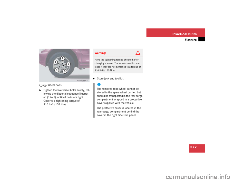
1-5Wheel bolts�
Tighten the five wheel bolts evenly, fol-
lowing the diagonal sequence illustrat-
ed (1 to 5), until all bolts are tight.
Observe a tightening torque of
110 lb-ft (150 Nm).
�
Store jack and tool kit.Warning!
G
Have the tightening torque checked after
changing a wheel. The wheels could come
loose if they are not tightened to a torque of
110 lb-ft (150 Nm).iThe removed road wheel cannot be
stored in the spare wheel carrier, but
should be transported in the rear cargo
compartment wrapped in a protective
cover supplied with the vehicle.
The protective cover is located in the
rear cargo compartment behind the
cover in the right side trim panel.
Page 283 of 344

283 Practical hints
Towing the vehicle
�Towing the vehicle
Mercedes-Benz recommends that the vehi-
cle be transported with all wheels off the
ground using flatbed or appropriate wheel
lift / dolly equipment. This method is pref-
erable to other types of towing.When circumstances do not permit the
recommended towing methods, the vehi-
cle may be towed with all wheels on the
ground only so far as necessary to have the
vehicle moved to a safe location where the
recommended towing methods can be em-
ployed.
!Use flatbed or wheel lift / dolly equip-
ment, with key in steering lock turned
to position0.
Do not tow with sling-type equipment.
Towing with sling-type equipment over
bumpy roads will damage radiator and
supports.
To prevent damage during transport,
do not tie down vehicle by its chassis or
suspension parts. Use the towing eyes.
Switch off the ESP (
�page 81),
tow-away alarm (
�page 85) and the
automatic central locking (
�page 93).
!When towing the vehicle with all wheels
on the ground, the gear selector lever
must be in positionN and the key must
be in steering lock position2.
When towing the vehicle with all wheels
on the ground, the vehicle may be
towed only for distances up to 30 miles
(50 km) and at a speed not to exceed
30 mph (50 km / h).
If the vehicle is towed with the front
axle raised (observe instructions re-
garding flexible drive shaft), the engine
must be shut off (key in steering lock
position1). Otherwise, the 4-ETS may
become engaged which may cause loss
of towing control.
!To be certain to avoid additional dam-
age to the vehicle powertrain, however
you should observe the following:�
With damage to the front axle�
raise front axle
�
remove flexible drive shaft be-
tween rear axle and transfer
case
�
With damage to the rear axle�
raise rear axle
�
tow vehicle with wheel lift or
dolly placed under front wheels
�
With damage to the transfer case�
remove flexible drive shaft to
the drive axles
Always install new self-locking nuts
when reinstalling flexible drive shaft.
Page 284 of 344

284 Practical hintsTowing the vehicleWarning!
G
If circumstances require towing the vehicle
with all wheels on the ground, always tow
with a tow bar if:�
the engine will not run
�
there is a malfunction in the power sup-
ply or in the vehicle’s electrical system
Prior to towing the vehicle with all wheels on
the ground, make certain that the key is in
steering lock position2.
If the key is left in steering lock position0
for an extended period of time, it can no
longer be turned in the switch. In this case,
the steering is locked. To unlock, remove
key from steering lock and reinsert.
Warning!
G
With the engine not running, there is no
power assistance for the brake and steering
systems. In this case, it is important to keep
in mind that a considerably higher degree of
effort is necessary to brake and steer the ve-
hicle. Adapt your driving accordingly.iTo signal turns while being towed with
hazard warning flasher in use, turn key
in steering lock to position2 and acti-
vate combination switch for left or right
turn signal in usual manner – only the
selected turn signal will operate.
Upon canceling the turn signal, the haz-
ard warning flasher will operate again.iThe vehicle cannot be started via
tow-start.
!When towing the vehicle with all wheels
on the ground, note the following:
With the automatic central locking acti-
vated and the key in steering lock
position2, the vehicle doors lock if the
left front wheel is turning at vehicle
speeds of approx. 9 mph (15 km / h) or
more.
To prevent the vehicle doors from lock-
ing, deactivate the automatic central
locking (
�page 93).
Towing of the vehicle should only be
done using the towing eye. Never at-
tach tow cable, tow rope or tow rod to
vehicle chassis, frame or suspension
parts.
Page 286 of 344
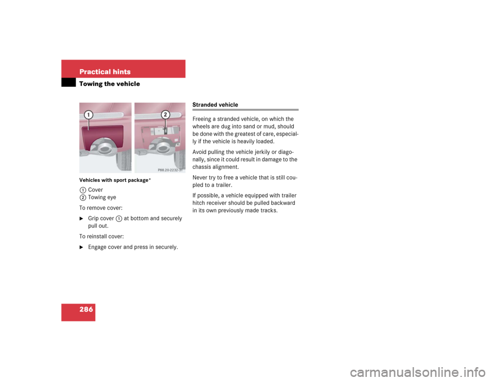
286 Practical hintsTowing the vehicleVehicles with sport package*1Cover
2Towing eye
To remove cover:�
Grip cover1 at bottom and securely
pull out.
To reinstall cover:
�
Engage cover and press in securely.
Stranded vehicle
Freeing a stranded vehicle, on which the
wheels are dug into sand or mud, should
be done with the greatest of care, especial-
ly if the vehicle is heavily loaded.
Avoid pulling the vehicle jerkily or diago-
nally, since it could result in damage to the
chassis alignment.
Never try to free a vehicle that is still cou-
pled to a trailer.
If possible, a vehicle equipped with trailer
hitch receiver should be pulled backward
in its own previously made tracks.
Page 295 of 344

295 Technical data
Rims and tires
�Rims and tires
Use only tires and rims which have been
specifically developed for your vehicle and
tested and approved by Mercedes-Benz.
Other tires and rims can have detrimental
effects, such as�
poor handling characteristics
�
increased noise
�
increased fuel consumption
Rims and tires
!Moreover, tires and rims not approved
by Mercedes-Benz may, under load, ex-
hibit dimensional variations and differ-
ent tire deformation characteristics
that could cause them to come into
contact with the vehicle body or axle
parts. This may result in damage to the
tires or the vehicle.
iFurther information on tires and rims is
available at any authorized
Mercedes-Benz Light Truck Center. A
tire inflation pressure table is located
on the fuel filler cap of the vehicle. The
tire pressure should be checked regu-
larly and should only be adjusted on
cold tires. Follow tire manufacturer’s
maintenance recommendation includ-
ed with vehicle.
Model
ML 350
ML 500
Rims (light alloy)
8J x 17 H2
81/2J x 17 H2
Wheel offset
2.0in (52mm)
2.0 in (52 mm)
All-season tires (radial-ply tires)
255 / 60 R17 106 H
275 / 55 R17 109 V
Rims* (light alloy)
81/2 J x 17 H2
81/2 J x 17 H2
Wheel offset*
1.85 in (47 mm)
1.85 in (47 mm)
All-season tires (radial-ply tires)*
275 / 55 R17 109 V
275 / 55 R17 109 V
Page 296 of 344
296 Technical dataRims and tiresSpare wheelModel
ML 350, ML 500
Rim
4Jx18 H2 ET0
Wheel offset
0 in (0 mm)
Space-saver tire
T155 / 90 D18 113M
1
1Must not be used with snow chains.

Space-saver tire
T155 / 90 D18 113M
1
1Must not be used with snow chains.")