Page 291 of 376
291 Practical hints
Unlocking/locking in an emergency
�
Insert a pin1, e.g. ball point pen, into
the covered opening.
�
Perform the following two steps simul-
taneously:�
Push pin1 down.
�
Move gear selector lever from
positionP.
�
Remove pin1.
The cover returns to its closed position af-
ter moving the gear selector lever to posi-
tions D+ and D-.iThe gear selector lever is locked again
when moving it to positionP.
Page 292 of 376
292 Practical hintsOpening/closing in an emergency
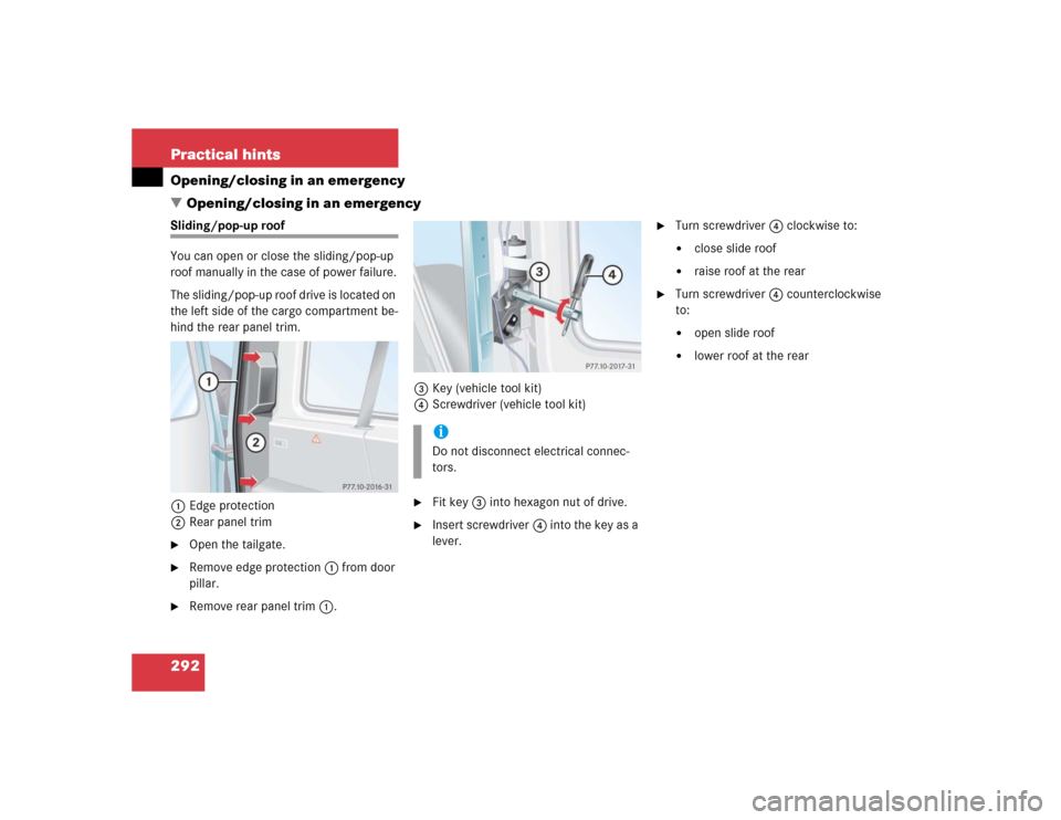
�Opening/closing in an emergencySliding/pop-up roof
You can open or close the sliding/pop-up
roof manually in the case of power failure.
The sliding/pop-up roof drive is located on
the left side of the cargo compartment be-
hind the rear panel trim.
1Edge protection
2Rear panel trim�
Open the tailgate.
�
Remove edge protection1 from door
pillar.
�
Remove rear panel trim1.3Key (vehicle tool kit)
4Screwdriver (vehicle tool kit)
�
Fit key3 into hexagon nut of drive.
�
Insert screwdriver4 into the key as a
lever.
�
Turn screwdriver4 clockwise to:�
close slide roof
�
raise roof at the rear
�
Turn screwdriver4 counterclockwise
to:�
open slide roof
�
lower roof at the rear
iDo not disconnect electrical connec-
tors.
Page 293 of 376
293 Practical hints
Brush guard*
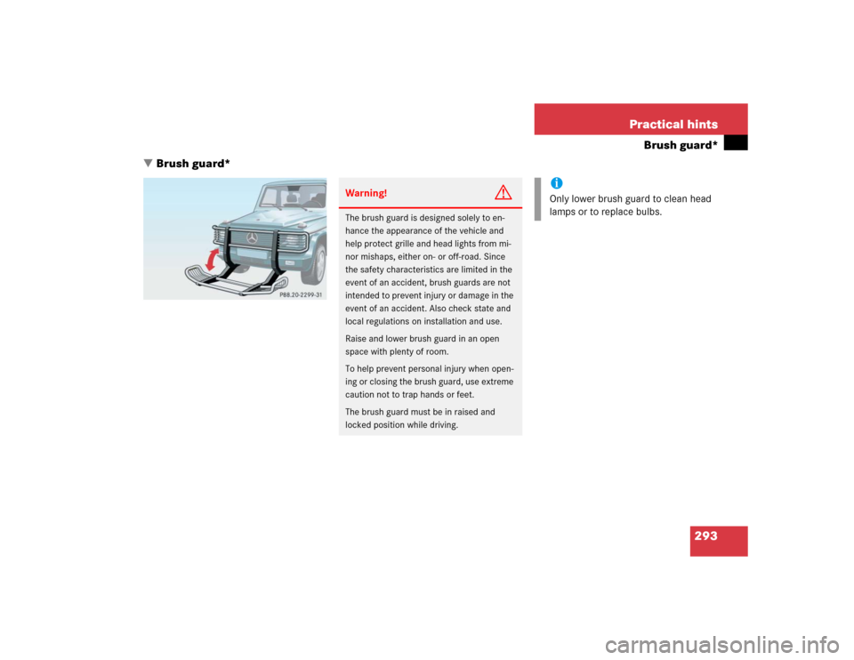
�Brush guard*
Warning!
G
The brush guard is designed solely to en-
hance the appearance of the vehicle and
help protect grille and head lights from mi-
nor mishaps, either on- or off-road. Since
the safety characteristics are limited in the
event of an accident, brush guards are not
intended to prevent injury or damage in the
event of an accident. Also check state and
local regulations on installation and use.
Raise and lower brush guard in an open
space with plenty of room.
To help prevent personal injury when open-
ing or closing the brush guard, use extreme
caution not to trap hands or feet.
The brush guard must be in raised and
locked position while driving.
iOnly lower brush guard to clean head
lamps or to replace bulbs.
Page 294 of 376
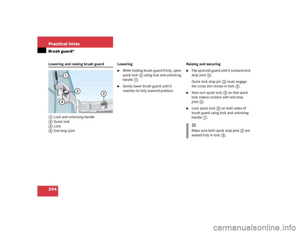
294 Practical hintsBrush guard*Lowering and raising brush guard
1Lock and unlocking handle
2Quick lock
3Lock
4End stop jointLowering
�
While holding brush guard firmly, open
quick lock2 using lock and unlocking
handle1.
�
Gently lower brush guard until it
reaches its fully lowered position.Raising and securing
�
Flip up brush guard until it contacts end
stop joint4.
Quick lock stop pin2 must engage
the cross slot recess in lock3.
�
Now turn quick lock2 so that quick
lock makes contact with end stop
joint4.
�
Lock quick lock2 on both sides of
brush guard using lock and unlocking
handle1.!Make sure both quick stop pins2 are
seated fully in lock3.
Page 298 of 376
298 Practical hintsReplacing bulbs1Protection cover
2Electrical connector (parking and
standing lamps)
3Electrical connector (high and low
beam)4Retainer spring
5Bulb for high and low beam
6Bulb socket for parking and standing
lamps
High and low beam bulb
�
Remove protection cover1.
�
Pull off electrical connector3.
�
Unclip retainer spring4.
�
Remove bulb5.
�
Insert new bulb so that the base lo-
cates in the recess on the holder.
�
Clip in retainer spring4.
�
Plug electrical connector3 onto
bulb5.
�
Press on protection cover1.
Parking and standing lamp bulb
�
Pull off electrical connector2 from
bulb socket6.
�
Push bulb into bulb socket6, turn
counterclockwise and remove.
�
Insert new bulb in bulb socket6, push
in and turn clockwise until it clicks in.
�
Plug electrical connector2 onto bulb
socket6.
Page 300 of 376
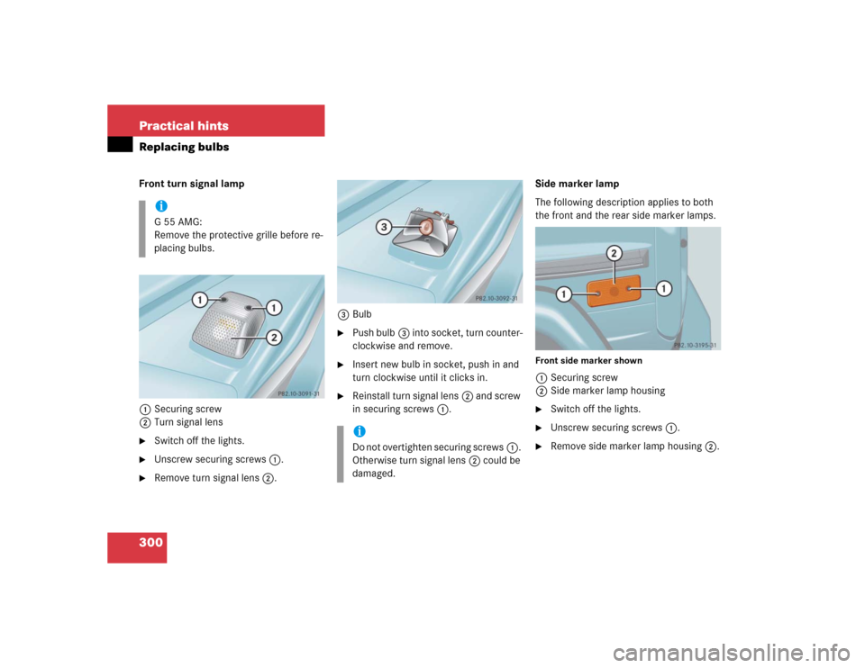
300 Practical hintsReplacing bulbsFront turn signal lamp
1Securing screw
2Turn signal lens�
Switch off the lights.
�
Unscrew securing screws1.
�
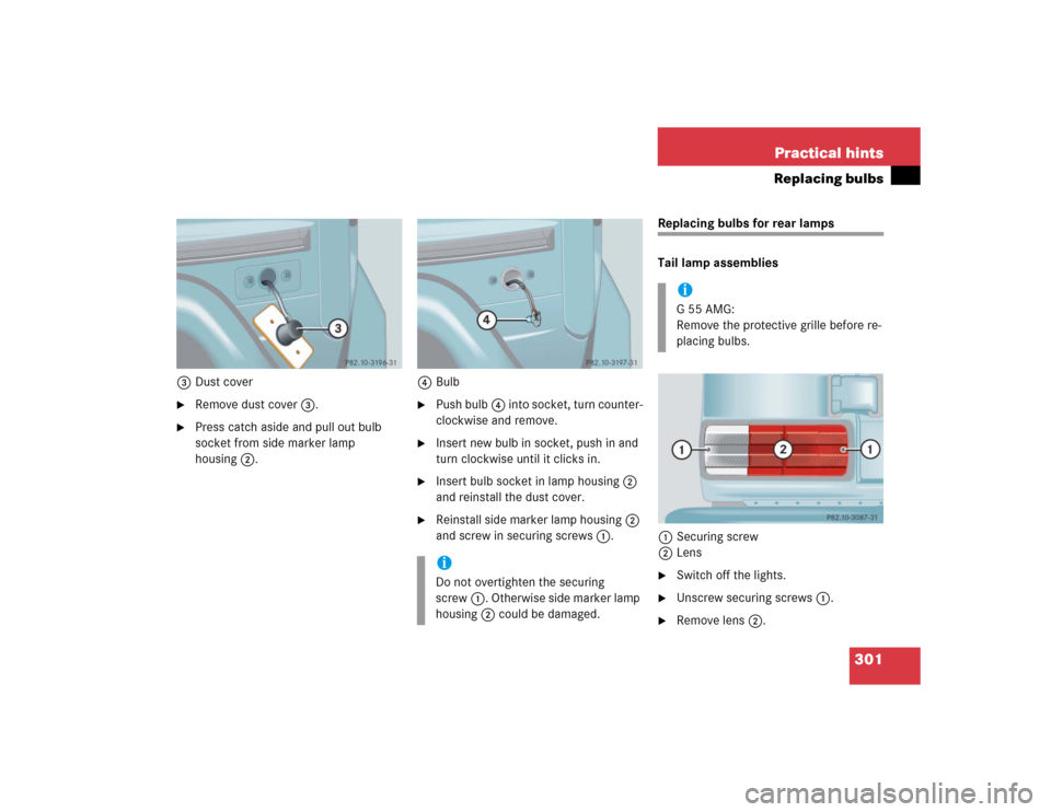
Remove turn signal lens2.3Bulb
�
Push bulb3 into socket, turn counter-
clockwise and remove.
�
Insert new bulb in socket, push in and
turn clockwise until it clicks in.
�
Reinstall turn signal lens2 and screw
in securing screws1.Side marker lamp
The following description applies to both
the front and the rear side marker lamps.
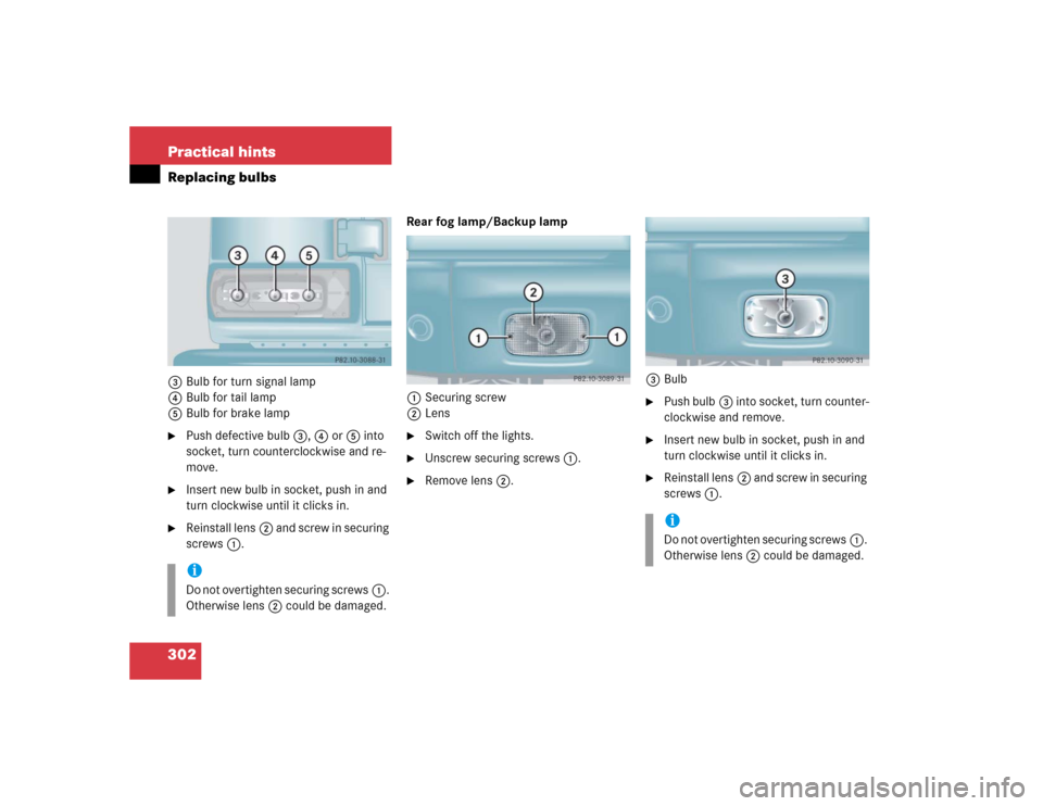
Front side marker shown1Securing screw
2Side marker lamp housing�
Switch off the lights.
�
Unscrew securing screws1.
�
Remove side marker lamp housing2.
iG55AMG:
Remove the protective grille before re-
placing bulbs.
iDo not overtighten securing screws1.
Otherwise turn signal lens2 could be
damaged.
Page 301 of 376
301 Practical hints
Replacing bulbs
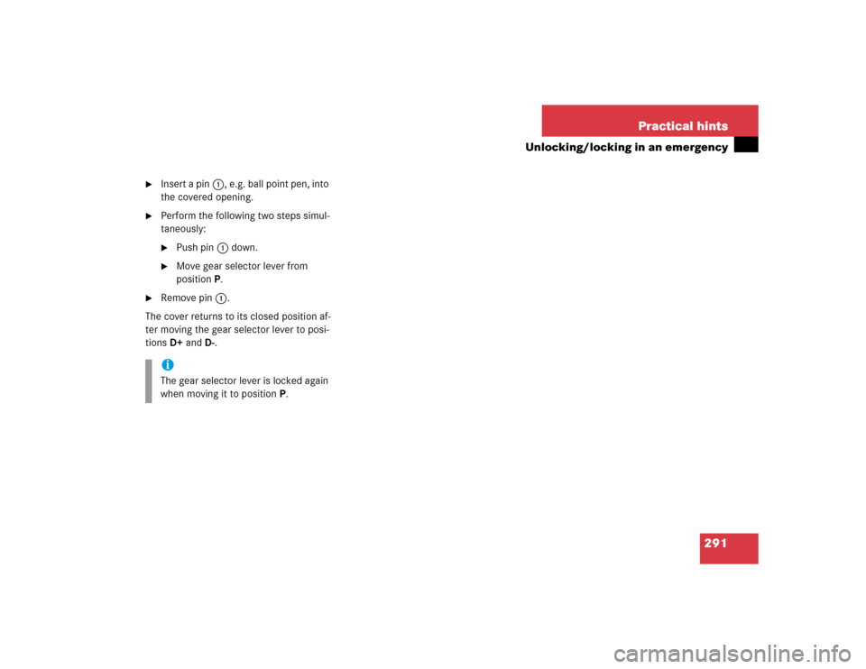
3Dust cover�
Remove dust cover3.
�
Press catch aside and pull out bulb
socket from side marker lamp
housing2.4Bulb
�
Push bulb4 into socket, turn counter-
clockwise and remove.
�
Insert new bulb in socket, push in and
turn clockwise until it clicks in.
�
Insert bulb socket in lamp housing2
and reinstall the dust cover.
�
Reinstall side marker lamp housing2
and screw in securing screws1.
Replacing bulbs for rear lamps
Tail lamp assemblies
1Securing screw
2Lens�
Switch off the lights.
�
Unscrew securing screws1.
�
Remove lens2.
iDo not overtighten the securing
screw1. Otherwise side marker lamp
housing2 could be damaged.
iG55AMG:
Remove the protective grille before re-
placing bulbs.
Page 302 of 376
302 Practical hintsReplacing bulbs3Bulb for turn signal lamp
4Bulb for tail lamp
5Bulb for brake lamp�
Push defective bulb3, 4 or5 into
socket, turn counterclockwise and re-
move.
�
Insert new bulb in socket, push in and
turn clockwise until it clicks in.
�
Reinstall lens2 and screw in securing
screws1.Rear fog lamp/Backup lamp
1Securing screw
2Lens
�
Switch off the lights.
�
Unscrew securing screws1.
�
Remove lens2.3Bulb
�
Push bulb3 into socket, turn counter-
clockwise and remove.
�
Insert new bulb in socket, push in and
turn clockwise until it clicks in.
�
Reinstall lens2 and screw in securing
screws1.
iDo not overtighten securing screws1.
Otherwise lens2 could be damaged.
iDo not overtighten securing screws1.
Otherwise lens2 could be damaged.

3Electrical connector (high and low
beam)4Retainer spring
5Bulb for high and low beam
6Bulb soc")