Page 368 of 442
368 Practical hintsFlat tire�
Unscrew the valve cap from tire
valve7.
�
Screw filler hosea onto tire valve7.
�
Insert electrical plug4 into vehicle
cigarette lighter socket.
�
Turn SmartKey in starter switch to
position1 (
�page 31).
or
�
Press the KEYLESS-GO* start / stop
button (
�page 33) on the selector le-
ver once. Do not depress brake pedal.
�
Press I on electric air pump switch8.
The electric air pump should now
switch on and inflate the tire.After five minutes, the pressure gauge
must display at least 26 psi (1.8 bar). The
air hose can become hot during inflation.
Please exercise appropriate caution.
�
If this tire pressure is not attained, turn
off the electric air pump, detach the fill-
er hose from the tire valve, and drive
vehicle back and forth very slowly ap-
proximately 30 ft (10 m).
This serves to better distribute the
TIREFIT sealant material inside the tire.
�
Unscrew the air pump’s air hose5
from flange6 of the TIREFIT contain-
er.
�
Screw air hose5 onto tire valve7.
Inflate the tire again.
�
After attaining a tire pressure of 26 psi
(1.8 bar), press 0 on electric air pump
switch8.
The electric air pump should now be
switched off.
iIf sealant has leaked out, let it dry. You
can then peel it off.
!Do not operate the electric air pump
longer than eight minutes without in-
terruption. Otherwise it may overheat.
You may operate the air pump again af-
ter it has cooled off.
Warning!
G
If a tire pressure of 26 psi (1.8 bar) is not at-
tained, tire is too severely damaged for
TIREFIT to provide a reliable tire repair.
In this case, TIREFIT cannot properly seal
the tire.
Do not drive the vehicle.
Contact the nearest Mercedes-Benz Center
or call Roadside Assistance.
Page 369 of 442
369 Practical hints
Flat tire
�
Turn SmartKey in starter switch to
position0 (
�page 31).
or
�
Press the KEYLESS-GO* start / stop
button (
�page 33) on the selector le-
ver twice. Do not depress brake pedal.
�
Detach the electric air pump.
The air hose may still be hot. Please ex-
ercise appropriate caution.
�
Store the electrical plug and the air
hose behind the flap and place the air
pump back in the trunk.
�
Close the trunk lid.
�
Drive away immediately.
The TIREFIT sealant will distribute itself
evenly inside the tire.
�
After driving vehicle for an initial
10 minutes, check tire pressure using
the pressure gauge on the air pump.Warning!
G
Do not exceed vehicle speed of 50 mph
(80 km / h). A TIREFIT repair is not designed
to operate at higher speeds.
The sticker must be attached on the instru-
ment cluster where it will be easily seen by
the driver.
Vehicle handling characteristics may
change. Adapt your driving accordingly.
Warning!
G
If tire pressure has fallen below
20 psi (1.3 bar) do not continue to drive the
vehicle.
Park your vehicle safely away from the road-
way and contact the nearest authorized
Mercedes-Benz Center or Roadside Assis-
tance.
If ti re pre ss ur e i s at l ea st 2 0 psi (1 .3 ba r ), in -
flate tire to correct pressure (see label on
fuel filler flap), and drive vehicle to nearest
tire repair facility to have tire repaired or re-
placed.
Recommended maximum duration of use:
300 miles (500 km) at 50 mph (80 km / h)
with the recommended tire pressure.
��
Page 370 of 442
370 Practical hintsFlat tire
�
Visit an authorized Mercedes-Benz
Center as soon as possible to obtain a
new TIREFIT container.
�
Bring used TIREFIT materials to an au-
thorized Mercedes-Benz Center for
proper disposal.
�
Replace your TIREFIT container every
four years. Replacement containers are
available at your authorized
Mercedes-Benz Center.
Mounting the spare wheel
Preparing the vehicle
Prepare the vehicle as described under
“Preparing the vehicle” on this page.�
Take the spare wheel out of the trunk
(�page 350).
Lifting the vehicle
�
Prevent the vehicle from rolling away
by blocking wheels with wheel chocks
(not included) or other sizable objects.
When changing wheel on a level surface:
�
Place one chock in front of and one be-
hind the wheel that is diagonally oppo-
site to the wheel being changed.
Warning!
G
Follow recommend inflation pressures.
Do not overinflate tires. Overinflating tires
can result in sudden deflation (blowout) be-
cause they are more likely to become punc-
tured or damaged by road debris, potholes
etc.
Do not underinflate tires. Underinflated tires
wear unevenly, adversely affect handling
and fuel economy, and are more likely to fail
from being overheated.
Do not overload the tires by exceeding the
specified vehicle capacity weight (as indicat-
ed by the label on the pillar in the driver’s
door opening). Overloading the tires can
overheat them, possibly causing a blowout.
Warning!
G
Do not exceed vehicle speed of 50 mph
(80 km / h). A TIREFIT repair is not designed
to operate at higher speeds.
The sticker must be attached on the instru-
ment cluster where it will be easily seen by
the driver.
Vehicle handling characteristics may
change. Adapt your driving accordingly.
��
Page 371 of 442
371 Practical hints
Flat tire
When changing wheel on a hill:�
Place chocks on the downhill side
blocking both wheels of the other axle.
�
Take the two-piece wheel wrench and
the jack out of the trunk (
�page 352).
Assemble wheel wrench.
�
On wheel to be changed, loosen but do
not yet remove the wheel bolts (ap-
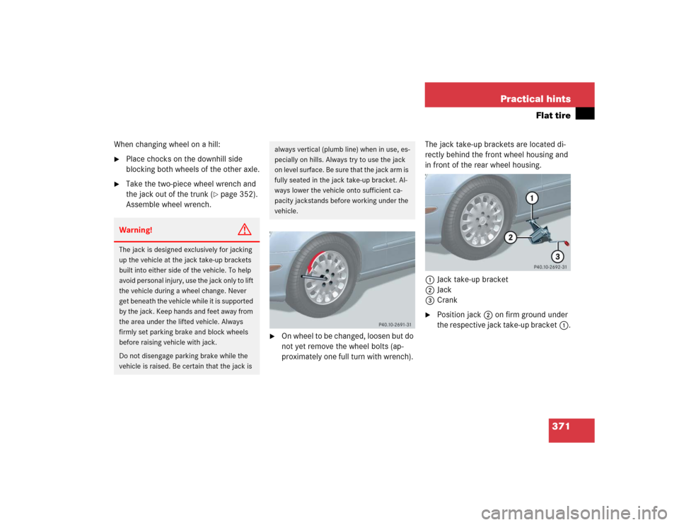
proximately one full turn with wrench). The jack take-up brackets are located di-
rectly behind the front wheel housing and
in front of the rear wheel housing.
1Jack take-up bracket
2Jack
3Crank
�
Position jack2 on firm ground under
the respective jack take-up bracket1.
Warning!
G
The jack is designed exclusively for jacking
up the vehicle at the jack take-up brackets
built into either side of the vehicle. To help
avoid personal injury, use the jack only to lift
the vehicle during a wheel change. Never
get beneath the vehicle while it is supported
by the jack. Keep hands and feet away from
the area under the lifted vehicle. Always
firmly set parking brake and block wheels
before raising vehicle with jack.
Do not disengage parking brake while the
vehicle is raised. Be certain that the jack is
always vertical (plumb line) when in use, es-
pecially on hills. Always try to use the jack
on level surface. Be sure that the jack arm is
fully seated in the jack take-up bracket. Al-
ways lower the vehicle onto sufficient ca-
pacity jackstands before working under the
vehicle.
Page 372 of 442
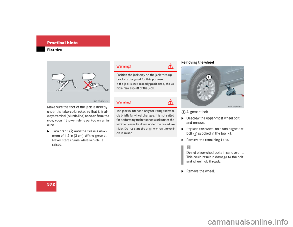
372 Practical hintsFlat tireMake sure the foot of the jack is directly
under the take-up bracket so that it is al-
ways vertical (plumb-line) as seen from the
side, even if the vehicle is parked on an in-
cline�
Turn crank3 until the tire is a maxi-
mum of 1.2 in (3 cm) off the ground.
Never start engine while vehicle is
raised.Removing the wheel
1Alignment bolt
�
Unscrew the upper-most wheel bolt
and remove.
�
Replace this wheel bolt with alignment
bolt1 supplied in the tool kit.
�
Remove the remaining bolts.
�
Remove the wheel.
Warning!
G
Position the jack only on the jack take-up
brackets designed for this purpose.
If the jack is not properly positioned, the ve-
hicle may slip off of the jack.Warning!
G
The jack is intended only for lifting the vehi-
cle briefly for wheel changes. It is not suited
for performing maintenance work under the
vehicle. Never lie down under the raised ve-
hicle. Do not start the engine when the vehi-
cle is raised.
!Do not place wheel bolts in sand or dirt.
This could result in damage to the bolt
and wheel hub threads.
Page 373 of 442
373 Practical hints
Flat tire
Mounting the Minispare wheel�
Clean contact surfaces of wheel and
wheel hub.
�
Guide the spare wheel onto the align-
ment bolt and push it on.
�
Insert wheel bolts and tighten them
slightly.
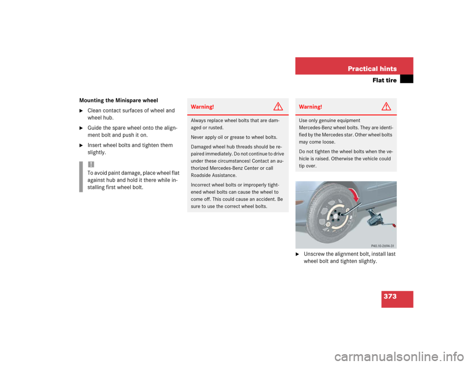
�
Unscrew the alignment bolt, install last
wheel bolt and tighten slightly.
!To avoid paint damage, place wheel flat
against hub and hold it there while in-
stalling first wheel bolt.
Warning!
G
Always replace wheel bolts that are dam-
aged or rusted.
Never apply oil or grease to wheel bolts.
Damaged wheel hub threads should be re-
paired immediately. Do not continue to drive
under these circumstances! Contact an au-
thorized Mercedes-Benz Center or call
Roadside Assistance.
Incorrect wheel bolts or improperly tight-
ened wheel bolts can cause the wheel to
come off. This could cause an accident. Be
sure to use the correct wheel bolts.
Warning!
G
Use only genuine equipment
Mercedes-Benz wheel bolts. They are identi-
fied by the Mercedes star. Other wheel bolts
may come loose.
Do not tighten the wheel bolts when the ve-
hicle is raised. Otherwise the vehicle could
tip over.
Page 374 of 442

374 Practical hintsFlat tireIn the case of a flat tire, you may tempo-
rarily use the Minispare wheel when ob-
serving the following restrictions:�
Do not exceed a vehicle speed of
50 mph (80 km / h).
�
Drive to the nearest tire repair facility
to have the flat tire repaired or re-
placed as appropriate.
�
Do not operate vehicle with more than
one spare wheel mounted.Lowering the vehicle
�
Lower vehicle by turning crank coun-
terclockwise until vehicle is resting ful-
ly on its own weight.
�
Remove the jack.
1-5 Wheel bolts
�
Tighten the five wheel bolts evenly, fol-
lowing the diagonal sequence illustrat-
ed (1 to 5), until all bolts are tight.
Observe a tightening torque of 96 lb-ft
(130 Nm).
�
Before storing the jack in the trunk, it
should be fully collapsed.
Warning!
G
The dimensions of the Minispare wheel are
different from those of the road wheels. As
a result, the vehicle handling characteristics
change when driving with a Minispare wheel
mounted.
The spare wheel should only be used tempo-
rarily, and replaced with a regular road
wheel as quickly as possible.
Warning!
G
Have the tightening torque checked after
changing a wheel. The wheels could come
loose if they are not tightened to a torque of
96 lb-ft (130 Nm).iWrap the damaged wheel in the protec-
tive film that comes with the spare
wheel and put the wheel in the trunk.
You can also place the damaged wheel
down into the spare wheel well. In this
case, you must stow the holder from
the spare wheel well in the trunk.
Do not activate the tire inflation pres-
sure monitor until the depressurized
tire is no longer in the vehicle.
Page 387 of 442
387 Technical data
Spare parts service
Warranty coverage
Identification labels
Layout of poly-V-belt drive
Engine
Rims and tires
Electrical system
Main dimensions
Weights
Fuels, coolants, lubricants etc.
Consumer information