Page 347 of 440

347 Practical hints
Unlocking/locking in an emergency
Fuel filler flap
In case the central locking system does
not release the fuel filler flap, you can open
it manually.�
Open trunk lid.
�
Remove right side trim panel in the
trunk.
�
Reach inside through opening2 in di-
rection of arrow.
�
Turn release knob 1 clockwise (ar-
row).
The fuel filler flap can be opened.Manually unlocking the gear selector
lever
In case of power failure, the gear selector
lever can be manually unlocked, e.g. to tow
the vehicle.�
Open the storage compartment under
the center armrest (
�page 246).
�
Take out cover 1.
�
Insert a pin into the opening of
division2 and pry the division out.
�
Insert a tool3 (e.g. screwdriver) into
the opening.
�
Perform the following two steps simul-
taneously:�
Push pin3 forward in the direction
of the arrow.
�
Move gear selector lever from
positionP.
�
Reinstall the division and cover after re-
moving the tool from the opening.iThe gear selector lever is locked again
when moving it to positionP.
Page 356 of 440
356 Practical hintsReplacing bulbsReplacing bulbs for rear lamps
Tail lamp assemblies
1Brake lamp
2Turn signal lamp
3Backup lamp
4Standing and side marker lamp
5Rear fog lamp (driver’s side)/tail�
Switch off the lights.
�
Open trunk.
�
Swing the trim panel covering the cor-
responding rear lights to the side.
�
Squeeze tabs together and remove the
bulb holder with the bulb.
�
Twist bulb counterclockwise and pull
out of bulb holder.
�
Insert new bulb into the holder and turn
it clockwise.
�
Reinstall bulb holder. The tabs must au-
dibly click.
�
Close trim panel.
�
Place the housing cover back on so
that its tabs click in place. License plate lamp
1Screws
�
Switch off the lights.
�
Loosen both screws1 and remove
lamp.
�
Replace the tubular lamp and reinstall
lamp.
�
Retighten the screws.
Page 358 of 440

358 Practical hintsFlat tire
�Flat tirePreparing the vehicle�
Park the vehicle as far as possible from
moving traffic on a hard surface.
�
Turn on the hazard warning flashers.
�
Engage the steering wheel lock in the
straight ahead position and set the
parking brake.
�
Move the gear selector lever toP.
�
Have any passenger exit the vehicle at
a safe distance from the roadway.
Mounting the Minispare wheelIn case of a flat tire, you may temporarily
use the spare wheel when observing the
following restrictions:
�
Do not exceed a vehicle speed of
50 mph (80 km/h).
�
Drive to the nearest tire repair facility
to have the flat tire repaired or re-
placed as appropriate.
�
Do not operate the vehicle with more
than one spare wheel mounted.
Prepare the vehicle as described on
(
�page 358).
�
Take the wheel wrench and the jack
out of the trunk (
�page 337).
�
Take the Minispare wheel and wheel
bolts out of the trunk (
�page 337).
Warning!
G
The dimensions of the Minispare wheel are
different from those of the road wheels. As
a result, the vehicle handling characteristics
change when driving with a Minispare wheel
mounted.
The spare wheel should only be used tempo-
rarily, and should be replaced with a regular
road wheel as quickly as possible.
Page 361 of 440
�
Clean contact surfaces")
361 Practical hints
Flat tire
Mounting the new wheel
1Wheel bolt for light alloy rims
2Wheel bolt for Minispare wheel or other
steel rims (located in trunk with spare
wheel)�
Clean contact surfaces of wheel and
wheel hub.
�
Guide the spare wheel onto the align-
ment bolt and push it on.
�
Insert wheel bolts and tighten them
slightly.
!Wheel bolts2 must be used when
mounting the Minispare wheel. The use
of any wheel bolts other than wheel
bolts2 for the Minispare will physical-
ly damage the vehicle's brakes.
!To avoid paint damage, place wheel flat
against hub and hold it there while in-
stalling first wheel bolt.Warning!
G
Always replace wheel bolts that are dam-
aged or rusted.
Never apply oil or grease to wheel bolts.
Damaged wheel hub threads should be re-
paired immediately. Do not continue to drive
under these circumstances! Contact an au-
thorized Mercedes-Benz Center or call
Roadside Assistance.
Incorrect wheel bolts or improperly tight-
ened wheel bolts can cause the wheel to
come off. This could cause an accident.
Make sure to use the correct wheel bolts.
��
Page 362 of 440
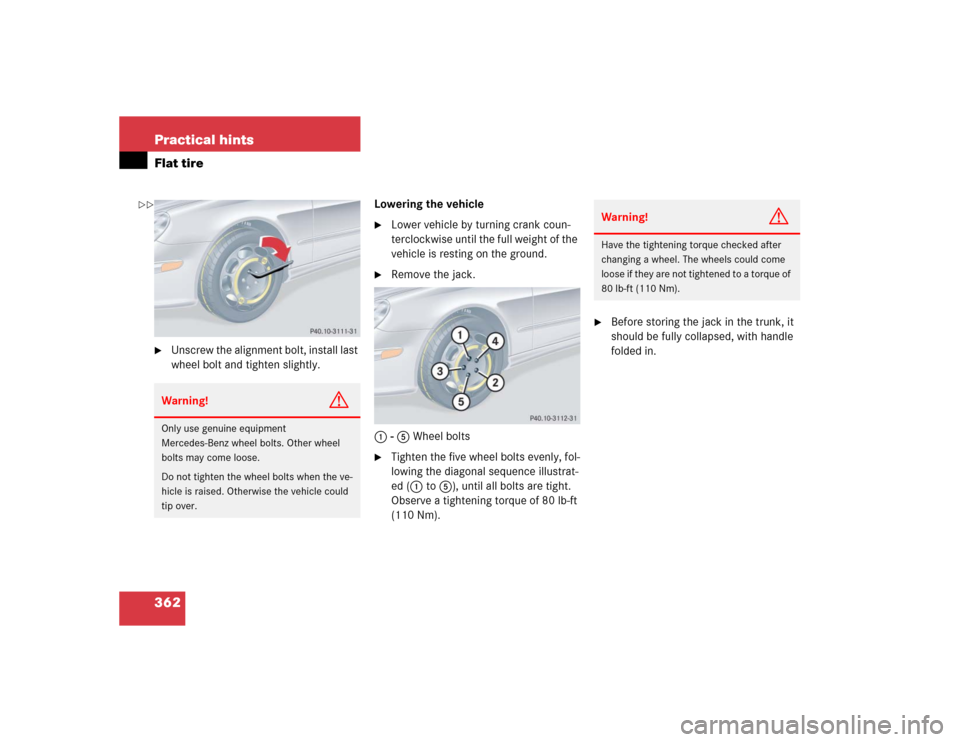
362 Practical hintsFlat tire�
Unscrew the alignment bolt, install last
wheel bolt and tighten slightly.Lowering the vehicle
�
Lower vehicle by turning crank coun-
terclockwise until the full weight of the
vehicle is resting on the ground.
�
Remove the jack.
1 - 5 Wheel bolts
�
Tighten the five wheel bolts evenly, fol-
lowing the diagonal sequence illustrat-
ed (1 to 5), until all bolts are tight.
Observe a tightening torque of 80 lb-ft
(110 Nm).
�
Before storing the jack in the trunk, it
should be fully collapsed, with handle
folded in.
Warning!
G
Only use genuine equipment
Mercedes-Benz wheel bolts. Other wheel
bolts may come loose.
Do not tighten the wheel bolts when the ve-
hicle is raised. Otherwise the vehicle could
tip over.
Warning!
G
Have the tightening torque checked after
changing a wheel. The wheels could come
loose if they are not tightened to a torque of
80 lb-ft (110 Nm).
��
Page 370 of 440

370 Practical hintsTowing the vehicle
Installing towing eye bolt
Towing eye bolt CLK 320/CLK 500
1Cover on right side of front bumper2Cover on right side of rear bumper
To remove cover:
�
Press mark on cover in direction of ar-
row.
�
Lift cover off to reveal threaded hole for
towing eye bolt.
The towing eye bolt is supplied with the
tool kit (located in the compartment under-
neath the trunk floor).
�
Screw towing eye bolt to its stop and
tighten with lug wrench.
To reinstall cover:
�
Fit cover and snap into place.
!When towing the vehicle with all wheels
on the ground, please note the follow-
ing:
With the automatic central locking acti-
vated and the SmartKey in starter
switch position2, or KEYLESS-GO*
start/stop button in position2, the ve-
hicle doors lock if the left front wheel
as well as the right rear wheel are turn-
ing at vehicle speeds of approx. 9 mph
(15 km / h) or more.
Switch off the tow-away alarm
(�page 83).
To prevent the vehicle door locks from
locking, deactivate the automatic cen-
tral locking (
�page 149).
Towing of the vehicle should only be
done using the properly installed tow-
ing eye bolt. Never attach tow cable,
tow rope or tow rod to the vehicle chas-
sis, frame or suspension parts.
iThe gear selector lever will remain
locked in positionP and the SmartKey
will not turn in the starter switch if the
battery is disconnected or discharged.
See notes on the battery (
�page 363)
or on jump starting (
�page 366).
Manually unlocking gear selector lever
(
�page 347)
Page 371 of 440

371 Practical hints
Towing the vehicle
Towing eye bolt CLK 55 AMG
Towing eye bolt in front bumper
The cover for the towing eye bolt in the
front bumper is identical to the cover on
the models CLK320/CLK500.
To remove and to reinstall cover,see “Tow-
ing eye bolt CLK 320/CLK 500”
(�page 370)Towing eye bolt in rear bumper
1Cover on right side of rear bumper
2Recess in the cover
To remove cover:
�
Insert flat, blunt object as a lever in re-
cess 2 on the edge of cover 1.
�
Loosen cover 1 from the bumper us-
ing lever, to reveal threaded hole for
towing eye bolt.
The towing eye bolt is supplied with the
tool kit (located in the compartment
underneath the trunk floor).
�
Screw towing eye bolt to its stop and
tighten with lug wrench.To reinstall cover:
�
Hook right-hand side of the cover into
opening.
�
Slide cover as far as it will go in the di-
rection of the arrow3.
�
Gently press left-hand side of cover in
direction of the arrow4.
The hooks on the left-hand side en-
gage.iWhen closing the cover, make sure the
cover’s check strap does not get
caught.
Page 374 of 440
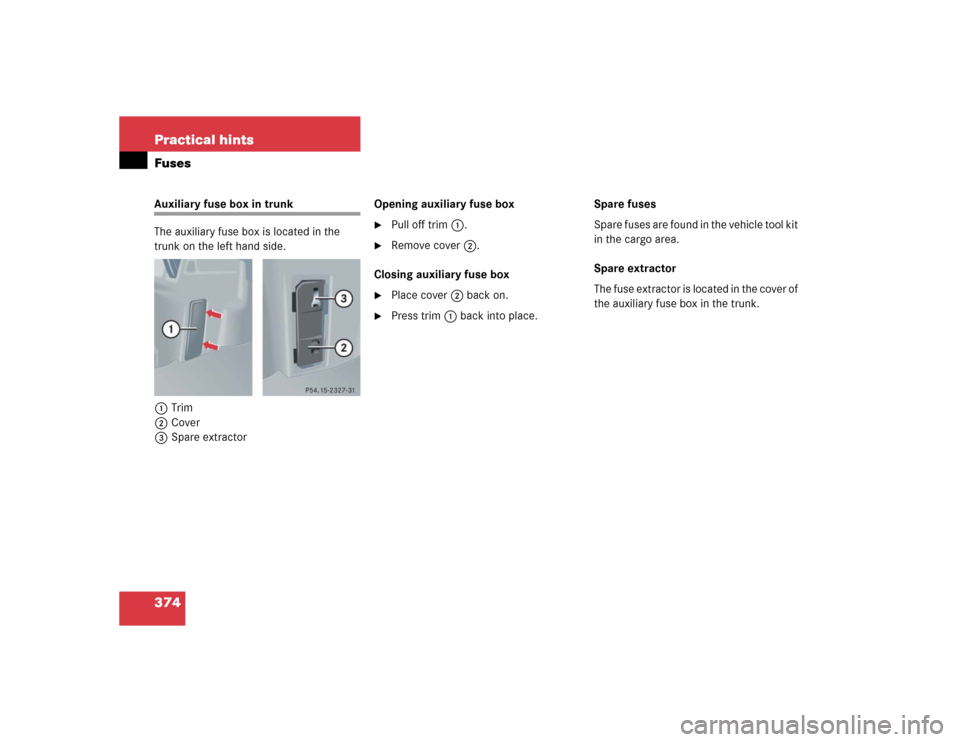
374 Practical hintsFusesAuxiliary fuse box in trunk
The auxiliary fuse box is located in the
trunk on the left hand side.
1Trim
2Cover
3Spare extractorOpening auxiliary fuse box
�
Pull off trim1.
�
Remove cover2.
Closing auxiliary fuse box
�
Place cover 2 back on.
�
Press trim1 back into place.Spare fuses
Spare fuses are found in the vehicle tool kit
in the cargo area.
Spare extractor
The fuse extractor is located in the cover of
the auxiliary fuse box in the trunk.