Page 23 of 400

23 At a glance
Instrument cluster
Item
Page
1
Left turn signal indicator
lamp
46
2
Speedometer
3
Right turn signal indicator
lamp
46
4
Fuel gauge with:Fuel reserve warning lamp
278
5
warning lamp
62,
278
1Supplemental
restraint system
indicator lamp
56,
278
6
Multifunction display
with:Trip odometer
109
Main odometer
111
Item
Page
Gear selector lever
position
43,
142
Program mode
143
Outside temperature
indicator
109
Digital clock
124
7
?Engine malfunction
indicator lamp
276
vElectronic Stability
Program (ESP)
warning lamp
76,
277
AHigh beam head-
lamp indicator
46,
103
EIndicator lamp
without function
1
DTRIndicator lamp
without function
1
1The indicator lamp illuminates with SmartKey in
starter switch position2. It sh ould go out when the
engine is running.
Item
Page
8
-Antilock Brake
System (ABS)
indicator lamp
74,
274
;Brake warning
lamp, USA only
44,
51,
275
3Brake warning
lamp, Canada only
44,
51,
275
9
Tachometer
109
a
Reset button for:�
Resetting trip
odometer
109
�
Resetting individual
settings
121
�
Instrument cluster
illumination
107
Page 107 of 400
.
The instrument cluster is activated when
you")
107 Controls in detail
Instrument cluster
�Instrument cluster
For a full view illustration of the instrument
cluster, see “At a glance” (
�page 22).
The instrument cluster is activated when
you
�
open a door
�
turn on the ignition
�
press the reset button (
�page 22)
�
switch on the exterior lamps
You can change the instrument cluster
settings in the Instrument cluster submenu
of the control system (
�page 124).
Instrument cluster illumination
Use the reset button (
�page 22) to adjust
the illumination brightness for the instru-
ment cluster.To brighten illumination
�
Turn the reset button in the instrument
cluster clockwise (
�page 22).
The instrument cluster illumination will
brighten.
To dim illumination
�
Turn the reset button in the instrument
cluster counterclockwise (
�page 22).
The instrument cluster illumination will
dim.
iThe instrument cluster illumination is
dimmed or brightened automatically to
suit ambient light conditions.
The instrument cluster illumination will
also be adjusted automatically when
you switch on the vehicle’s exterior
lamps.
Page 111 of 400

111 Controls in detail
Control system
�Control system
The control system is activated as soon as
the SmartKey in the starter switch is
turned to position1. The control system
enables you to�
call up information about your vehicle
�
change vehicle settings
For example, you can use the control
system to find out when your vehicle is
next due for service, to set the language
for messages in the instrument cluster
display, and much more.
The control system relays information to
the multifunction display.
Multifunction display
1Outside temperature
2Main odometer
3Trip odometer
4Automatic transmission program mode
5Current gear selector lever position
6Digital clock
iThe displays for the audio systems
(radio, CD player, cassette player) will
appear in English, regardless of the
language selected.
Warning!
G
A driver’s attention to the road and traffic
conditions must always be his/her primary
focus when driving.
For your safety and the safety of others,
selecting features through the multifunction
steering wheel should only be done by the
driver when traffic and road conditions
permit it to be done safely.
Bear in mind that at a speed of just 30 mph
(approximately 50 km/h), your vehicle is
covering a distance of 44 feet
(approximately 13.5 m) every second.
Page 302 of 400
302 Practical hintsWhere will I find ...?Operational position�
Turn crank handle clockwise until it
engages (operational position).
Before storing the vehicle jack in its
compartment:
�
It should be fully collapsed.
�
The handle must be folded in (storage
position).
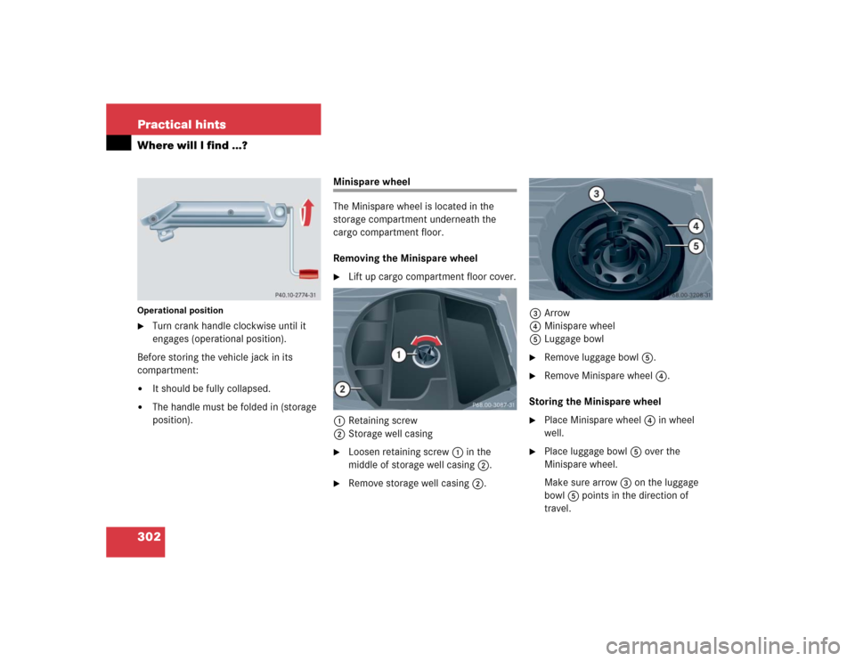
Minispare wheel
The Minispare wheel is located in the
storage compartment underneath the
cargo compartment floor.
Removing the Minispare wheel�
Lift up cargo compartment floor cover.
1Retaining screw
2Storage well casing
�
Loosen retaining screw1 in the
middle of storage well casing2.
�
Remove storage well casing2.3Arrow
4Minispare wheel
5Luggage bowl
�
Remove luggage bowl5.
�
Remove Minispare wheel4.
Storing the Minispare wheel
�
Place Minispare wheel4 in wheel
well.
�
Place luggage bowl5 over the
Minispare wheel.
Make sure arrow3 on the luggage
bowl5 points in the direction of
travel.
Page 303 of 400

303 Practical hints
Where will I find ...?
�
Place storage well casing2 over the
luggage bowl5 and turn retaining
screw1 clockwise as far as it will go
to secure the Minispare wheel.In the case of a flat tire, you may
temporarily use the Minispare wheel when
observing the following restrictions:
�
Do not exceed a vehicle speed of
50 mph (80 km/h).
�
Drive to the nearest tire repair facility
to have the flat tire repaired or
replaced as appropriate.
�
Do not operate vehicle with more than
one Minispare wheel mounted.
For more information, see “Rims and Tires”
(
�page 341).
iArrow3 on luggage bowl5 must
point in the direction of travel. Other-
wise you cannot place the storage well
casing2 on top and secure the
Minispare wheel with the retaining
screw1.
Warning!
G
The dimensions of the Minispare wheel are
different from those of the road wheels. As
a result, the vehicle handling characteristics
change when driving with a Minispare wheel
mounted.
The Minispare wheel should only be used
temporarily, and should be replaced with a
regular road wheel as quickly as possible.
Page 308 of 400

308 Practical hintsUnlocking/locking in an emergencyFuel filler flap
In case the central locking system does
not release the fuel filler flap, you can open
it manually.�
Open the tailgate.
�
Press button1.
�
Fold down trim panel2.
�
Reach inside through opening3 in
direction of arrow.
�
Turn release knob4 clockwise
(arrow).
The fuel filler flap can now be opened.Manually unlocking the transmission
gear selector lever
In the case of power failure the transmis-
sion gear selector lever can be manually
unlocked, e.g. to tow the vehicle.
1Coin holder
2Tool
�
Open the storage compartment in front
of the center armrest (
�page 217).
�
Release coin holder1 (e.g. using a
small coin).
�
Swing coin holder1 aside.
�
Insert a tool2 (e.g. flat blade
screwdriver) into the opening.
�
Perform the following two steps
simultaneously:�
Push tool2 down.
�
Move gear selector lever from
positionP.
�
Reinstall coin holder1 after removing
tool2 from the opening.iThe gear selector lever is locked again
when moving it to positionP.
Page 309 of 400
309 Practical hints
Opening/closing in an emergency
�Opening/closing in an emergency
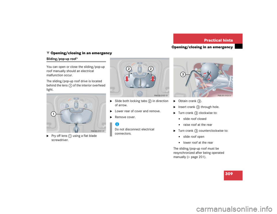
Sliding/pop-up roof*
You can open or close the sliding/pop-up
roof manually should an electrical
malfunction occur.
The sliding/pop-up roof drive is located
behind the lens1 of the interior overhead
light.�
Pry off lens1 using a flat blade
screwdriver.
�
Slide both locking tabs2 in direction
of arrow.
�
Lower rear of cover and remove.
�
Remove cover.
�
Obtain crank3.
�
Insert crank3 through hole.
�
Turn crank3 clockwise to:�
slide roof closed
�
raise roof at the rear
�
Turn crank3 counterclockwise to:�
slide roof open
�
lower roof at the rear
The sliding/pop-up roof must be
resynchronized after being operated
manually (
�page 201).
iDo not disconnect electrical
connectors.
Page 312 of 400

312 Practical hintsReplacing bulbsReplacing bulbs for front lamps
Halogen headlamps
1Bulb socket for turn signal lamp
2Headlamp cover for high beam head-
lamp and for parking and standing
lamp
3Headlamp cover for low beam head-
lamp4Low beam bulb
5High beam bulb
6Bulb socket for parking and standing
lamp
Low and high beam bulb
�
Switch off the lights.
�
Open the hood (
�page 252).
�
Press the clamp and remove headlamp
cover2 or3.
�
Pull electrical connector off.
�
Unclip the retainer springs and take out
the bulb.
�
Insert the new bulb so that the base
locates in the recess on the holder.
�
Clip the retainer springs and plug the
connector onto the bulb.
�
Align headlamp cover2 or3 and
click into place.
Front turn signal lamp bulb
�
Switch off the lights.
�
Open the hood (
�page 252).
�
Twist bulb socket1 counterclockwise
and pull out.
�
Push bulb into socket, turn counter-
clockwise and remove.
�
Insert new bulb in socket, push in and
twist clockwise.
�
Reinsert bulb socket in lamp and twist
clockwise.