Page 169 of 227
6 - 18 Roadside Emergency
Side marker – bulb renewal
Remove the side marker lamp by sliding it upwards to compress
the spring clips. While still holding the lamp up, against the
spring clips, gently ease the bottom of the lamp from the
bumper. Remove the lamp.
Twist the bulb holder anti-clockwi se to remove it from the lamp
assembly.
Fit a new bulb of the correct type, W5W to the bulb holder.
Position the bulb holder to th e lamp assembly and twist it
clockwise to refit it.
Carefully press the lamp assembly into the recess until it clicks
into place.
Page 170 of 227

Roadside Emergency 6 - 19
Rear light assembly – bulb renewal
On the rear light assemblies, only the direction indicator,
reverse and fog bulbs are replaceable. The stop/tail lamps
consist of arrays of LED lights which can only be renewed by a
Jaguar Retailer if they fail to operate.
Ensure that the lights and ig nition switch are OFF before
removing any bulbs.
Open the trunk and secure the floor panel in the open position.
See page 6 - 4.
Rotate fastener ( A) a quarter turn and remove. Pull back the
side carpet trim to access the rear of the light assembly.
The bulb positions are:
1. Reverse light, type P21W.
2. Direction indicator, type PY21W.
3. Fog light, type P21W.
Rotate the bulb/connector and wi thdraw it from the assembly.
Remove the faulty bulb and fit a new one of the correct type,
as illustrated on the bulb holder. It is essential to fit the correct
type.
Reposition the bulb/connector and turn it to secure.
Carefully refit the side carpet trim. Fit fastener ( A) and rotate a
quarter turn.
Close the trun k floor panel.
Page 171 of 227

6 - 20 Roadside Emergency
Fire Extinguisher
Many countries make it compulsory to
carry a fire extinguisher. Your Jaguar
Retailer can supply and fit one.
Mexican vehicles have a factory fitted fire
extinguisher which contains 2.2 lbs (1 kg)
of BC powder pressurised with nitrogen
to a working pressure of 180 psi (12 bar)
at 68°F (20°C).
This extinguisher can be used on liquid
fires, electrical equipment fires and, if no
explosion risk, gaseous fires.
!WARNING:
1. Do not test the fire extinguisher prior to use. Partial discharge will
render the extinguisher
inoperative.
2. Do not use the fire extinguisher closer than 8 feet (2.4 m) to the
base of a liquid fire as the force
may splatter the burning liquid to
the surrounding area. To operate the fire extinguisher:
1. Unclip and remove the extinguisher
from the bracket.
2. Put your finger through the yellow safety wedge ring ( A) and pull hard to
remove the wedge. The operating
lever will be exposed.
3. Hold the extinguisher upright and aim at the base of the fire.
4. Press the lever down firmly.
5. Release the lever to stop the flow of powder. Maintenance
Every six months:
• Remove the extinguisher from its
bracket and check that the nozzle is
clear.
• Check that the safety wedge strap ( B)
is secure.
• Check the pressure gauge on the base of the extinguisher. If the gauge is in
the red area report it to your Jaguar
Retailer immediately as the
extinguisher may not work in an
emergency.
Page 172 of 227

Roadside Emergency 6 - 21
Fuses and Fuse Boxes
Do not fit a new fuse if the wiring is
damaged; contact a Jaguar Retailer.
After renewing a fuse have the circuit
checked by a Jaguar Retailer.
Two types of fuses are fitted in the fuse
boxes, ATO type and Midi type.
Spare fuses and a special tool for
removing and replacing fuses are located
on a removable panel clipped to the rear
of the trunk ( A).
Use only the spare fuses supplied. If a
spare fuse is used, renew it with a Jaguar
approved fuse of the same amperage
rating.
Checking and Renewing a
Blown Fuse
Make sure the new fuse is the correct
rating (amperage).
Fuses are colour coded according to the
amperage and the rating is also marked
on each fuse.
Caution: When a fuse box lid is
removed, take care to protect the box
from moisture, and refit the lid at the
earliest opportunity. ATO-fuse replacement
Push the tool on to the suspect ATO fuse
and withdraw the fuse. If the wire in the
fuse is broken, the fuse has blown.
Fit a new fuse using the tool.
Midi fuse replacement
(not shown)
Unscrew the two nuts and remove the
fuse. Note that the fuse is supplied
directly from the battery +ve; take care
not to short a spanner or other metal tool
to the chassis when removing the nuts.!WARNING:
1. Do not fit a fuse of a different amperage from that removed.
The electrical circuits may
become overloaded with the
subsequent possibility of a fire.
2. No attempt should be made to repair a fuse that has blown as this
may cause a fire hazard or serious
damage elsewhere in the
electrical circuit.
Page 173 of 227

6 - 22 Roadside Emergency
Fuse Box Locations
There are three separate fuse boxes fitted
to the vehicle, each one containing fuses
protecting a different group of circuits.
Engine compartment fuse box
The fuse box is located in the engine
compartment on the right-hand side
adjacent to the windscreen wash
reservoir.
Remove the fuse box lid by pressing the
spring catch and lifting.
When refitting, press the fuse box lid in
the area of the retaining lugs until the lid
engages. Cabin fuse box
The cabin fuse box is located behind the
right-hand side trim panel in the footwell.
To access the fuse box, pull out the
bottom of the trim panel (arrowed), slide
the panel down slightly and remove.
Trunk fuse box
A fuse box is located in the trunk,
situated behind the battery.
Open the trunk floor panel to gain access
to the fuse box.
Remove the fuse box lid by pulling the
retaining clips and pulling the lid
upwards.
Reposition the lid and press down until
the retaining clips engage.
Replace the floor panel.
Page 174 of 227
Roadside Emergency 6 - 23
Fuse Positions
A – Trunk fuse box
B – Cabin fuse box
C – Engine compartment fuse box
Page 175 of 227
6 - 24 Roadside Emergency
Engine compartment fuse boxFuse No Fuse
Type Rating
(amps) Colour
Circuit
F1 ATO 10A Red Front ignition, UHEGO, fu el pump, rear ignition relay coils
F2 – F3 Not used
F4 ATO 30A Green Powerwash pump
F5 Not used
F6 ATO 40A Orange Air suspension compressor
F7 ATO 40A Orange Right-hand front screen heater or wiper park zone heater
F8 ATO 20A Yellow Right-hand dipped beam
F9 ATO 20A Yellow Left-hand dipped beam
F10, F11 Not used
F12 ATO 10A Red Engine control module
F13 ATO 10A Red Fuel injectors
F14 ATO 10A Red Purge valve, EGR valve, canister close valve (CCV), port deactivation, V6 intake manifold
tuning valves (IMTV), MAFS, air filter solenoid, radiator fan controller
F15 Not used
F16 ATO 20A Yellow Right-hand main beam, left-hand main beam
F17 ATO 10A Red Engine control module, transmission control module
F18 ATO 15A Blue Front fog lights, instrument cluster front fog status
Page 176 of 227
Roadside Emergency 6 - 25
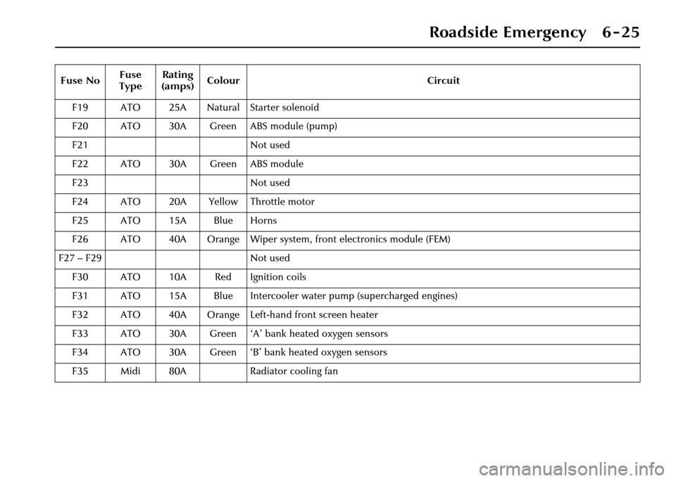
F19 ATO 25A Natural Starter solenoid
F20 ATO 30A Green ABS module (pump)
F21 Not used
F22 ATO 30A Green ABS module
F23 Not used
F24 ATO 20A Yellow Throttle motor
F25 ATO 15A Blue Horns
F26 ATO 40A Orange Wiper system, front electronics module (FEM)
F27 – F29 Not used F30 ATO 10A Red Ignition coils
F31 ATO 15A Blue Intercooler water pump (supercharged engines)
F32 ATO 40A Orange Left-hand front screen heater
F33 ATO 30A Green ‘A’ bank heated oxygen sensors
F34 ATO 30A Green ‘B’ bank heated oxygen sensors
F35 Midi 80A Radiator cooling fan
Fuse No
Fuse
Type Rating
(amps) Colour Circuit