Page 1936 of 4264

Valve opening vacuum kPa (psi) 1.96 �
�� � 4.91 (0.28
�
�� � 0.71)
110RS006
Radiator Core
1. A bent fin may result in reduced ventilation and
overheating m")
6B-12 ENGINE COOLING (6VE1 3.5L)
Valve opening vacuum kPa (psi) 1.96 �
�� � 4.91 (0.28
�
�� � 0.71)
110RS006
Radiator Core
1. A bent fin may result in reduced ventilation and
overheating may occur. All bent fins must be
straightened. Pay close attention to the base of the
fin when it is being straightened.
2. Remove all dust, bugs and other foreign material.
Flushing the Radiator
Thoroughly wash the inside of the radiator and the
engine coolant passages with cold water and mild
detergent. Remove all signs of scale and rust.
Cooling System Leakage Check
Use a radiator cap tester to force air into the radiator
through the filler neck at the specified pressure of 196
kPa (28.5 psi) with a cap tester:
Leakage from the radiator
Leakage from the coolant pump
Leakage from the water hoses
Check the rubber hoses for swelling.
Cap tester: 5–8840–0277–0
Adapter: 5–8840–2603–0
110RS005
Installation
1. Install radiator assembly (9) with hose, taking care
not to damage the radiator core with a fan blade.
2. Support the radiator upper tank with the bracket (5)
and secure the radiator.
3. Connect reserve tank hose (6).
4. Install lower fan guide (3).
5. Connect radiator inlet hose and outlet hose (1) to
the engine.
Page 1937 of 4264
 6B-13
6. Connect oil cooler hose to automatic transmission.
RTW36BSH000101
7. Connect battery ground cable.
8. Pour engine coolant up to filler neck of radiat")
ENGINE COOLING (6VE1 3.5L) 6B-13
6. Connect oil cooler hose to automatic transmission.
RTW36BSH000101
7. Connect battery ground cable.
8. Pour engine coolant up to filler neck of radiator, and
up to MAX mark of reserve tank.
RTW36BSH000101
Important operation (in case of 100% engine
coolant change) procedure for filling with engine
coolant.
Engine coolant change
1. To change engine coolant, make sure that the
engine is cool.
WARNING: When the coolant is heated to a high
temperature, be sure not to loosen or remove the
radiator cap. Otherwise you might get scalded by
hot vapor or boiling water. To open the radiato
r
cap, put a piece of thick cloth on the cap and
loosen the cap slowly to reduce the pressure when
the coolant has become cooler.
2. Open radiator cap and drain the cooling system by
loosening the drain valve on the radiator and on the
cylinder body.
NOTE: For best result it is suggested that the engine
cooling system be flushed at least once a year. It is
advisable to flash the interior of the cooling system
including the radiator before using anti-freeze
(ethylene-glycol based).
Replace damaged rubber hoses as the engine
anti-freeze coolant is liable to leak out even mino
r
cracks.
Isuzu recommends to use Isuzu genuine anti-freeze
(ethylen-glycol based) or equivalent, for the cooling
system and not add any inhibitors or additives.
CAUTION: A failure to correctly fill the engine
cooling system in changing or topping up coolant
may sometimes cause the coolant to overflow from
the filler neck even before the engine and radiato
r
are completely full.
If the engine runs under this condition, shortage o
f
coolant may possibly result in engine overheating.
To avoid such trouble, the following precautions
should be taken in filling the system.
3. To refill engine coolant, pour coolant up to filler neck
using a filling hose which is smaller in outside
diameter of the filler neck. Otherwise air between
the filler neck and the filling hose will block entry,
preventing the system from completely filling up.
4. Keep a filling rate of 9 liter/min. or less. Filling ove
r
this maximum rate may force air inside the engine
and radiator.
And also, the coolant overflow will increase, making
it difficult to determine whether or not the system is
completely full.
5.
After filling the system to the full, pull out the filling
hose and check to see if air trapped in the system is
disclodged and the coolant level goes down. Should
the coolant level go down, repeat topping-up until
there is no more drop in the coolant level.
Page 1938 of 4264

6. After directly filling the radiator, fill the reservoir to
the maximum level.
7. Install and tighten radiator cap and start the engine.
After idling for 2 to 3")
6B-14 ENGINE COOLING (6VE1 3.5L)
6. After directly filling the radiator, fill the reservoir to
the maximum level.
7. Install and tighten radiator cap and start the engine.
After idling for 2 to 3 minutes, stop the engine and
reopen radiator cap. If the water level is lower,
replenish.
WARNING: When the coolant is heated to a high
temperature, be sure not to loosen or remove the
radiator cap. Otherwise you might get scalded by
hot vapor or boiling water. To open the radiato
r
cap, put a piece of thick cloth on the cap and
loosen the cap slowly to reduce the pressure when
the coolant has become cooler.
8.
After tightening radiator cap, warm up the engine at
about 2,000 rpm.
Set heater adjustment to the highest temperature
position, and let the coolant circulate also into
heater water system.
9. Check to see the thermostat has opened through
the needle position of water thermometer, conduct a
5-minute idling again and stop the engine.
10. When the engine has been cooled, check filler neck
for water level and replenish if required. Should
extreme shortage of coolant is found, check the
coolant system and reservoir tank hose for leakage.
11. Fill the coolant into the reservoir tank up to “MAX"
line.
Page 1939 of 4264
 6B-15
Drive Belt and Cooling Fan
Drive Belt and Associated Parts
015RW005
Legend (4) Water Pump and Cooling Fan Pulley
(1) Crankshaft Pulley (5) Idle Pulley")
ENGINE COOLING (6VE1 3.5L) 6B-15
Drive Belt and Cooling Fan
Drive Belt and Associated Parts
015RW005
Legend (4) Water Pump and Cooling Fan Pulley
(1) Crankshaft Pulley (5) Idle Pulley
(2) Generator (6) Tension Pulley
(3) Power Steering Pump (7) Drive Belt
The drive belt adjustment is not required as automatic
drive belt tensioner is equipped.
Inspection
Check drive belt for wear or damage, and replace with a
new one as necessary.
Installation
Install cooling fan assembly and tighten bolts/nuts to the
specified torque.
Torque : 25 N�
�� �m (2.5 kg�
�� �m/18 lb ft) for fan pulley
and fan bracket.
Torque : 10 N�
�� �m (1.0 kg�
�� �m/7 lb ft) for fan and
clutch assembly.
NOTE: Fan belts for 6VE1 Gasoline Engine mounted on
98MY (UX) have been brought into one. As a result, the
rotating direction of a fan belt is opposite to the direction
of cooling fan for 92 to 97MY 6VD1 with no
interchangeability.
Therefore, incorrect installation of a fan may cause the
air for cooling to flow in the opposite direction, this
resulting in the poor performance of the air-conditione
r
and a rise temperature in engine cooling water.
Page 1940 of 4264
6B-16 ENGINE COOLING (6VE1 3.5L)
Main Data and Specifications
General Specifications
M/T A/T
Cooling system Engine coolant forced circulation
Radiator Tube type corrugated
Heat radiation capacity 81.4 kw (70.004 kcal/h)
Heat radiation area 9.42m� (0.875ft�)
Radiator front area 0.28m� (0.026ft�)
Radiator dry weight 5.0kg (11.0lb) 5.2kg (11.4lb)
Radiator cap valve opening pressure 93.3 � 122.7kpa (13.5 � 17.8psi)
Engine coolant pump Centrifugal impeller type
Delivery 300 (317) or more
Pump speed 5000 � 50 rpm
Thermostat Wax pellet type with air hole
Valve opening temperature 74.5 � 78.5�C (166.1 � 173.3�F)
Engine coolant total capacity 12.3lit (13.0U.S qt) 12.2lit (12.9U.S qt)
Page 1941 of 4264
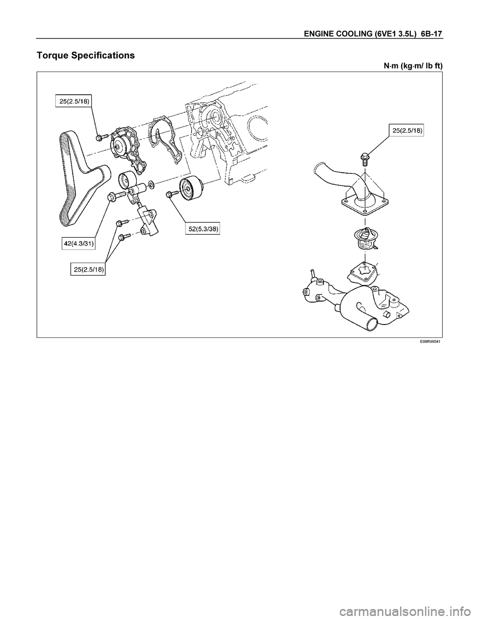
ENGINE COOLING (6VE1 3.5L) 6B-17
Torque Specifications
N�
�� �m (kg�
�� �m/ lb ft)
E06RW041
Page 1942 of 4264
6B-18 ENGINE COOLING (6VE1 3.5L)
Special Tools
ILLUSTRATION PART NO.
PART NAME
5–8840–277–0
(J–24460–01)
Tester; radiator cap
5-8840-2603-0
(J–33984–A)
Adapter; radiator cap
Page 2055 of 4264
 deposits on the portion of the spark
plug in the cylinder. Excessive idling a")
3.5L ENGINE DRIVEABILITY AND EMISSIONS 6E-59
Carbon fouling of the spark plug is indicated by dry,
black carbon (soot) deposits on the portion of the spark
plug in the cylinder. Excessive idling and slow speeds
under light engine loads can keep the spark plug
temperatures so low that these deposits are not burned
off. Very rich fuel mixtures or poor ignition system
output may also be the cause. Refer to DTC P0172.
Oil fouling of the spark plug is indicated by wet oily
deposits on the portion of the spark plug in the cylinder,
usually with little electrode wear. This may be caused by
oil during break-in of new or newly overhauled engines.
Deposit fouling of the spark plug occurs when the
normal red-brown, yellow or white deposits o
f
combustion by products become sufficient to cause
misfiring. In some cases, these deposits may melt and
form a shiny glaze on the insulator around the cente
r
electrode. If the fouling is found in only one or two
cylinders, valve stem clearances or intake valve seals
may be allowing excess lubricating oil to enter the
cylinder, particularly if the deposits are heavier on the
side of the spark plug facing the intake valve.
TS23995
Excessive gap means that the air space between the
center and the side electrodes at the bottom of the
spark plug is too wide for consistent firing. This may be
due to excessive wear of the electrode during use.
A
check of the gap size and comparison to the gap
specified for the vehicle in Maintenance and Lubrication
will tell if the gap is too wide. A spark plug gap that is
too small may cause an unstable idle condition.
Excessive gap wear can be an indication of continuous
operation at high speeds or with engine loads, causing
the spark to run too hot. Another possible cause is an
excessively lean fuel mixture.
TS23992
Low or high spark plug installation torque or improper
seating can result in the spark plug running too hot and
can cause excessive center electrode wear. The plug
and the cylinder head seats must be in good contact fo
r
proper heat transfer and spark plug cooling. Dirty or
damaged threads in the head or on the spark plug can
keep it from seating even though the proper torque is
applied. Once spark plugs are properly seated, tighten
them to the torque shown in the Specifications Table.
Low torque may result in poor contact of the seats due
to a loose spark plug. Over tightening may cause the
spark plug shell to be stretched and will result in poo
r
contact between the seats. In extreme cases, exhaus
t
blow-by and damage beyond simple gap wear may
occur.
Cracked or broken insulators may be the result o
f
improper installation, damage during spark plug heat
shock to the insulator material. Upper insulators can be
broken when a poorly fitting tool is used during
installation or removal, when the spark plug is hit from
the outside, or is dropped on a hard surface. Cracks in
the upper insulator may be inside the shell and no
t
visible. Also, the breakage may not cause problems
until oil or moisture penetrates the crack later.

Main Data and Specifications
General Specifications
M/T A/T
Cooling system Engine coolant forced circulation
Radiator Tube type corrugated
Heat radiation c")

Special Tools
ILLUSTRATION PART NO.
PART NAME
5–8840–277–0
(J–24460–01)
Tester; radiator cap
5-8840-2603-0
(J–33984–A)
Adapte")