Page 2859 of 4264

ENGINE EXHAUST 6F-3
When inspecting or replacing exhaust system components,
make sure there is adequate clearance from all points on the
underbody to prevent overheating the floor pan and possible
damage to the passenger compartment insulation and trim
materials.
Check complete exhaust system and nearby body areas and
rear compartment lid for broken, damaged, missing or
mispositioned parts, open seams, holes, loose connections or
other deterioration which could permit exhaust fumes to seep
into the rear compartment or passenger compartment. Dust or
water in the rear compartment may be an indication of a
problem in one of these areas. Any faulty areas should be
corrected immediately.
Hangers
Various types of hangers are used to support exhaust
system(s). These include conventional rubber straps, rubber
rings, and rubber blocks.
The installation of exhaust system supports is very important,
as improperly installed supports can cause annoying vibrations
which can be difficult to diagnose.
Three Way Catalytic Converter (If applicable)
The three way catalytic converter is an emission control device
added to the exhaust system to reduce pollutants from the
exhaust gas stream.
CAUTION: The catalytic converter requires the use of
unleaded fuel only.
Periodic maintenance of the exhaust system is not required. If
the vehicle is raised for other service, it is advisable to check
the condition of the complete exhaust system.
A dual bed monolith catalytic converter is used in combination
with three way catalytic converter.
Catalytic Types:
Three way (Reduction/Oxidation) catalyst
The catalyst coating on the three way (reduction) converter
contains platinum and rhodium which lowers the levels of
nitrous oxide (NOx) as well as hydrocarbons (HC) and carbon
monoxide (Co).
Gasket
The gasket must be replaced whenever a new exhaust pipe,
muffler or catalytic converter is installed.
Page 2990 of 4264

Items followed by an asterisk (*) require more frequent maintenance if the vehicle is driven under severe conditions.
Ref")
0B-2 MAINTENANCE AND LUBRICATION
MAINTENANCE SCHEDULE (For GENERAL EXPORT)
Items followed by an asterisk (*) require more frequent maintenance if the vehicle is driven under severe conditions.
Refer to "SEVERE CONDITIONS MAINTENANCE SCHEDULE."
I : Inspect and correct or replace as necessary A : Adjust
R : Replace or change T : Tighten to specified torque L : Lubricate
SERVICE INTERVAL:
� 1,000 km 5 10 15 20 25 30 35 40 45 50 55 60 65 70 75 80 85 90 95 100(Use odometer reading � 1,000 miles 3 6 9 12 15 18 21 24 27 30 33 36 39 42 45 48 51 54 57 60or months whichever
comes fi rst)
or months 6 12 18 24 30 36 42 48 54 60 66 72 78 84 90 96 102 108 114 120
ENGINE Idling speed and acceleration
(GASOLINE) I I - I - I - I - I - I - I - I - I - I
(DIESEL) I I I I I I I I I I I I I I I I I I I I * Air cleaner element
(GASOLINE) - I - I - I - R - I - I - I - R - I - I
(DIESEL) I I I I I I I R I I I I I I I R I I I I * P Engine oil (6VE1) - R - R - R - R - R - R - R - R - R - R * P Engine oil (C24SE) Replace every 12,000km * D Engine oil (4JH1-TC) - R - R - R - R - R - R - R - R - R - R * D Engine oil (4JA1-TC) - - R - - R - - R - - R - - R - - R - - * D Engine oil (4JA1-T) RR R R RR RRRRRRRR R R R RRR * P Engine oil filter (6VE1) - R - R - R - R - R - R - R - R - R - R * P Engine oil filter (C24SE) Replace every 12,000km * D Engine oil filter (4JH1-TC, 4JA1-T) - R - R - R - R - R - R - R - R - R - R * D Engine oil filter (4JA1-TC) - - R - - R - - R - - R - - R - - R - - Oil leakage and contamination
(GASOLINE) - I - I - I - I - I - I - I - I - I - I
(DIESEL) I I I I I I I I I I I I I I I I I I I I Fuel leakage I I - I - I - I - I - I - I - I - I - I Fuel tank - - - | - - - | - - - | - - - | - - - | P O2 Sensor Replace every 160,000km P Valve clearances (6VE1) Check and adjust if noisy D Valve clearances A - - A - - - A - - - A - - - A - - - A P Spark plugs (C24SE) (for leaded
fuel use) - R - R - R - R - R - R - R - R - R - R
P Spark plugs (C24SE) (for unleaded
fuel use) - - - - - R - - - - - R - - - - - R - -
P Spark plugs (6VE1) Replace every 160,000km Spark plug wire | | - | - | - | - | - | - | - | - | - | Fuel filter (GASOLINE) - - - R - - - R - - - R - - - R - - - R Fuel filter (DIESEL) - - R - - R - - R - - R - - R - - R - - Engi ne / Accessory dri ve belt
(GASOLINE) - - - - - - - - - R - - - - - - - - - R
Fan belt tension and damage
(DIESEL) I I I I I I I I I I I I I I I I I I I I
* Exhaust system I I - I - I - I - I - I - I - I - I - I Engine coolant concentration (6VE1) - - - - - - - - - R - - - - - - - - - R (C24SE) - | - | - | - | - R - | - | - | - | - R Engine coolant level concentration
(DESEL) I I I I I I I I I R I I I I I I I I I R
Cooli ng sy stem for water l eakage - I - I - I - I - I - I - I - I - I - I All hoses and pipes in engine
compartment for clogs or damage - I - I - I - I - I - I - I - I - I - I
P Timing belt (C24SE) - - - - - - - - - - - - - - - I - - - - (Replace every 120,000km) P Timing belt (6VE1) Replace every 160,000km CLUTCH Cl utch fl ui d I I - I - I - I - I - I - I - I - I - I Clutch pedal travel and free play I I - I - I - I - I - I - I - I - I - I
Page 3060 of 4264
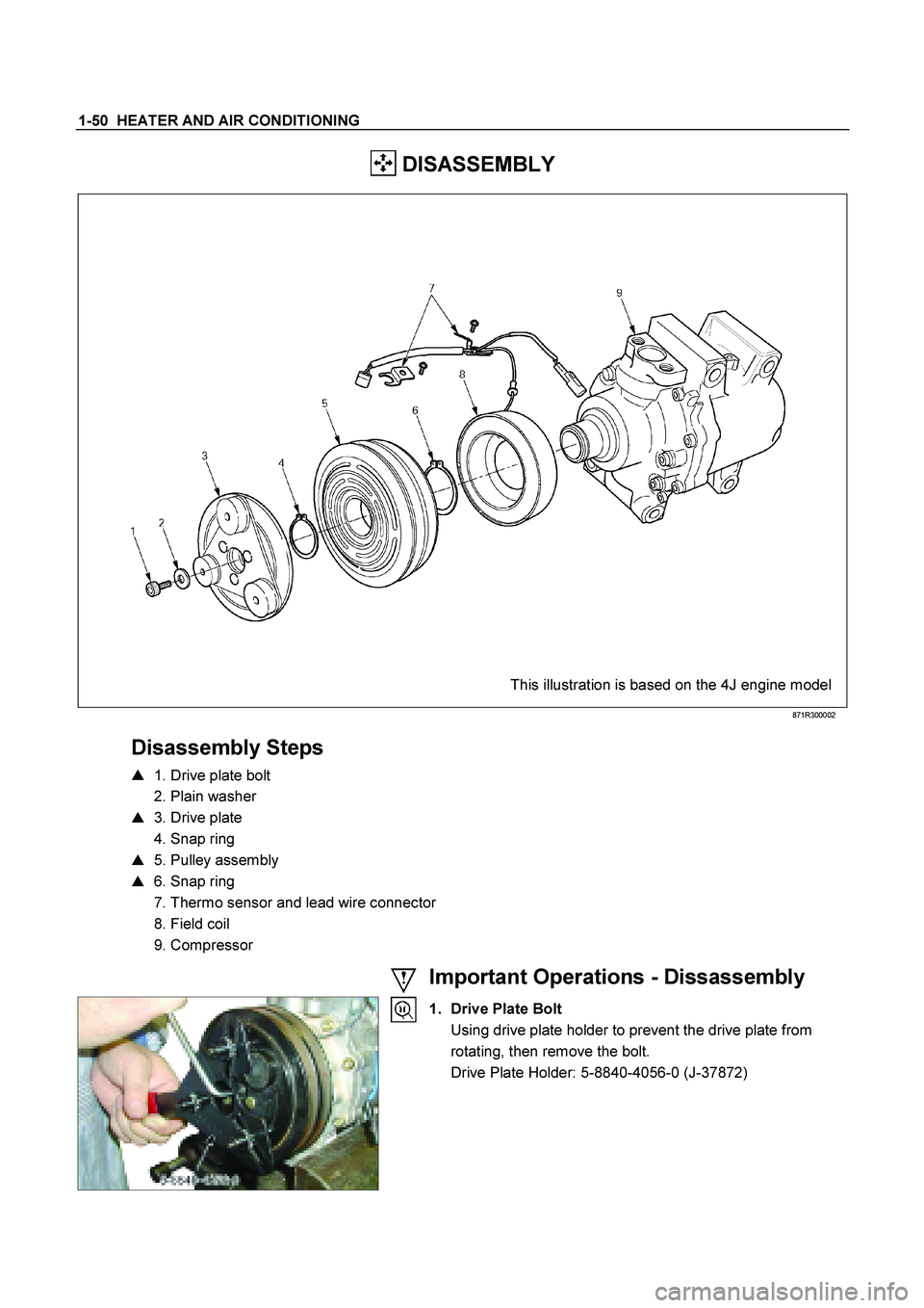
1-50 HEATER AND AIR CONDITIONING
DISASSEMBLY
This illustration is based on the 4J engine model
871R300002
Disassembly Steps
� 1. Drive plate bolt
2. Plain washer
� 3. Drive plate
4. Snap ring
� 5. Pulley assembly
� 6. Snap ring
7. Thermo sensor and lead wire connector
8. Field coil
9. Compressor
Important Operations - Dissassembly
1. Drive Plate Bolt
Using drive plate holder to prevent the drive plate from rotating, then remove the bolt.
Drive Plate Holder: 5-8840-4056-0 (J-37872)
Page 3062 of 4264
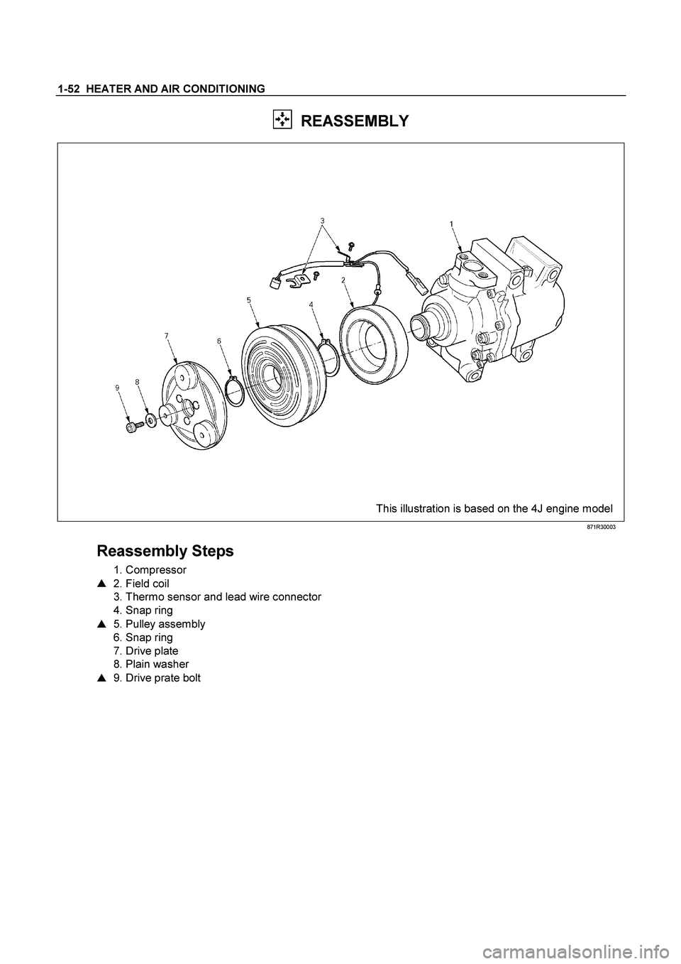
1-52 HEATER AND AIR CONDITIONING
REASSEMBLY
This illustration is based on the 4J engine model
871R30003
Reassembly Steps
1. Compressor
� 2. Field coil
3. Thermo sensor and lead wire connector
4. Snap ring
� 5. Pulley assembly
6. Snap ring
7. Drive plate
8. Plain washer
� 9. Drive prate bolt
Page 3462 of 4264
3B-32 POWER-ASSISTED STEERING SYSTEM
Inflator Module
Inflator Module and Associated Parts
430R300013
Legend
(1) Horn Lead
(2) SRS Connector
(3) Steering Wheel
(4) Steering Wheel Fixing Nut
(5) Inflator Module or Horn Pad
Page 3464 of 4264
3B-34 POWER-ASSISTED STEERING SYSTEM
10. Loosen the horn pad fixing screw at the rear of the
steering wheel (without SRS air bag).
430R300009
11. Disconnect the SRS air bag connector and horn
lead connector located behind the air bag assembl
y
and remove the air bag assembly. (with SRS air
bag)
060R300041
12. Remove the horn pad and the horn leads at the
center of the wheel (without SRS air bag).
NOTE: It removes previosly from the spoke bottom.
RTW43BSH000201
WARNING: THE INFLATOR MODULE SHOULD
ALWAYS BE CARRIED WITH THE COVER AWAY
FROM YOUR BODY AND SHOULD ALWAYS BE
LAID ON A FLAT SURFACE WITH THE COVER SIDE
UP. THIS IS NECESSARY BECAUSE A FREE SPACE
IS PROVIDED TO ALLOW THE AIR CUSHION TO
EXPAND IN THE UNLIKELY EVENT OF
ACCIDENTAL DEPLOYMENT. OTHERWISE,
PERSONAL INJURY MAY RESULT. (with SRS ai
r
bag)
430R300007
Page 3465 of 4264

The inflator module consists of a cover, air bag, inflator,
and retainer. Inspect the inflator module mainly for the
f")
POWER-ASSISTED STEERING SYSTEM 3B-35
Inspection and Repair (with SRS air
bag)
The inflator module consists of a cover, air bag, inflator,
and retainer. Inspect the inflator module mainly for the
following:
��
Check for holes, cracks, severe blemishes and
deformation on the cover.
��
Check that the retainer is not deformed.
��
Check for defects such as damage and breakage in
the lead wire for the igniter.
If an abnormality is found as the result of the inspection,
replace the inflator module with a new one.
Installation
1. Support the inflator module and carefully connect the
SRS connector and horn lead. (with SRS air bag)
060R300041
2. Connect the horn leads at center of wheel. (without
SRS air bag)
NOTE: Horn leads is letting a bracket top pass.
(Plastic type steering wheel only)
RTW43BSH000301
3. Push the born pad area 1-4.
Tighten the born pad fixing screw to the specifed
torque (without SRS air bag)
Torque: 2 - 4 N�
�� �
m (0.2 – 0.4 kg�
�� �
m/17 - 35 lb ft)
NOTE: A horn pad is not struck at the time o
f
attachment.
RTW43BSH000401
Page 3467 of 4264
POWER-ASSISTED STEERING SYSTEM 3B-37
Steering Wheel
Steering Wheel and Associated Parts
430R300013
Legend
(1) Horn Lead
(2) SRS Connector
(3) Steering Wheel
(4) Steering Wheel Fixing Nut
(5) Inflator Module or Horn Pad
Removal
1. Turn the steering wheel so that the vehicle's wheels
are pointing straight ahead.
2. Turn the ignition switch to "LOCK".
3. Disconnect the battery "-" terminal cable, and wait a
t
least 5 minutes. (with SRS air bag)
4.
Disconnect the yellow 2-way SRS connector located
under the steering column. (with SRS air bag)
CAUTION: The wheels of the vehicle must be
straight ahead and the steering column in the
"LOCK" position before disconnecting the steering
wheel. Failure to do so will cause the coil assembly
to become uncentered which will cause damage to
the coil assembly. (with SRS air bag)
5. Disable the SRS (Refer to "Disabling the SRS" in
this section). (with SRS air bag)
 Horn Lead
(2) SRS Connector
(3) Steering Wheel
(4) Steering Wheel Fixing")
.
430R300009
11. Disconnect the SRS air bag connector and horn
lead")
 Horn Lead
(2) SRS Connector
(3) Steering Wheel
(4) Steering Wheel Fixing Nut")