Page 1920 of 4264
6A-96 ENGINE MECHANICAL (6VE1 3.5L)
Crankshaft main bearing, Flywheel, Crankcase, Oil pan, Timing belt tensioner, Timing pulley, timing belt
cover, Oil pump, Oil gallery, Oil strainer and water pump
N�
�� �m (kg�
�� �m/ lb ft)
RTW46ALF000701
Page 1921 of 4264
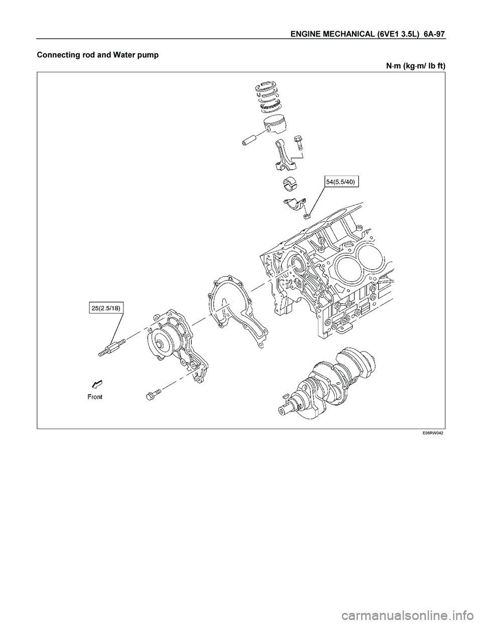
ENGINE MECHANICAL (6VE1 3.5L) 6A-97
Connecting rod and Water pump
N�
�� �m (kg�
�� �m/ lb ft)
E06RW042
Page 1925 of 4264
 6B-1
ENGINE
ENGINE COOLING (6VE1 3.5L)
CONTENTS
Service Precaution............................................. 6B–1
General Description .........................")
ENGINE COOLING (6VE1 3.5L) 6B-1
ENGINE
ENGINE COOLING (6VE1 3.5L)
CONTENTS
Service Precaution............................................. 6B–1
General Description ........................................... 6B–2
Diagnosis ........................................................... 6B–5
Draining and Refilling Cooling System .............. 6B–6
Water Pump ...................................................... 6B–7
Water Pump and Associated Parts ................ 6B–7
Removal ......................................................... 6B–7
Inspection ....................................................... 6B–7
Installation....................................................... 6B–7
Thermostat ........................................................ 6B–9
Thermostat and Associated Parts .................. 6B–9
Removal ......................................................... 6B–9
Inspection ....................................................... 6B–9
Installation ...................................................... 6B–9
Radiator ............................................................. 6B–10
Radiator and Associated Parts ....................... 6B–10
Removal ......................................................... 6B–11
Inspection ....................................................... 6B–11
Installation ...................................................... 6B–12
Drive Belt and Cooling Fan ................................ 6B–15
Drive Belt and Associated Parts ..................... 6B–15
Inspection ....................................................... 6B–15
Installation ...................................................... 6B–15
Main Data and Specifications ............................ 6B–16
Special Tool .................................................... 6B–18
Service Precaution
WARNING: THIS VEHICLE HAS A SUPPLEMENTAL
RESTRAINT SYSTEM (SRS). REFER TO THE SRS
COMPONENT AND WIRING LOCATION VIEW IN
ORDER TO DETERMINE WHETHER YOU ARE
PERFORMING SERVICE ON OR NEAR THE SRS
COMPONENTS OR THE SRS WIRING. WHEN YOU
ARE PERFORMING SERVICE ON OR NEAR THE
SRS COMPONENTS OR THE SRS WIRING, REFE
R
TO THE SRS SERVICE INFORMATION. FAILURE TO
FOLLOW WARNINGS COULD RESULT IN
POSSIBLE AIR BAG DEPLOYMENT, PERSONAL
INJURY, OR OTHERWISE UNNEEDED SRS SYSTEM
REPAIRS.
CAUTION: Always use the correct fastener in the
proper location. When you replace a fastener, use
ONLY the exact part number for that application.
ISUZU will call out those fasteners that require a
replacement after removal. ISUZU will also call out
the fasteners that require thread lockers or thread
sealant. UNLESS OTHERWISE SPECIFIED, do not
use supplemental coatings (Paints, greases, o
r
other corrosion inhibitors) on threaded fasteners or
fastener joint interfaces. Generally, such coatings
adversely affect the fastener torque and the joint
clamping force, and may damage the fastener.
When you install fasteners, use the correct
tightening sequence and specifications. Following
these instructions can help you avoid damage to
parts and systems.
Page 1926 of 4264
6B-2 ENGINE COOLING (6VE1 3.5L)
General Description
030RW001
Legend (7)Cylinder Head
(1) Water Pump (8) Right Bank
(2) Thermostat (9) Throttle Body
(3) Radiator (10) Cylinder Block
(4) Reserve Tank (11) Cylinder Head
(5) Cooling Fan (12) Left Bank
(6) Cylinder Block (13) Heater
The engine cooling system consists of the radiator, the
water pump, the cooling fan, and the thermostat.
To quickly increase cold engine coolant temperature fo
r
smooth engine operation, the coolant is circulated by
the water pump and thermostat through the bypass
hose and back to the cylinder body.
The coolant does not circulate through the radiator.
When the coolant temperature reaches specified value,
the thermostat will begin to open and a gradually
increasing amount of coolant will circulate through the
radiator.
The thermostat will be fully open when the coolan
t
temperature reaches specified value. All of the coolant
is now circulating through the radiator for effective
engine cooling.
Page 1927 of 4264
ENGINE COOLING (6VE1 3.5L) 6B-3
Water Pump
The EC pump is a centrifugal impeller type and is driven
by a timing belt.
030RS001
Thermostat
The thermostat is a wax pellet type with a air hole(1)
and is installed in the thermostat housing.
031RW002
Radiator
The radiator is a tube type with corrugated fins. In order
to raise the boiling point of the coolant, the radiator is
fitted with a cap in which the valve is operated at 93.3
�
122.7 kPa (13.5 � 17.8 psi) pressure. (No oil cooler
provided for M/T)
110RS001
Antifreeze Solution
Calculating mixing ratio
F06RW005
Page 1931 of 4264
 6B-7
Water Pump
Water Pump and Associated Parts
030RS002
Legend
(1) Timing Belt (3) Water Pump Assembly
(2) Idle Pulley (4) Gasket
Removal
1. Disco")
ENGINE COOLING (6VE1 3.5L) 6B-7
Water Pump
Water Pump and Associated Parts
030RS002
Legend
(1) Timing Belt (3) Water Pump Assembly
(2) Idle Pulley (4) Gasket
Removal
1. Disconnect battery ground cable.
2. Drain coolant.
3. Radiator hose (on inlet pipe side).
4. Remove timing belt. Refer to “Timing Belt" in this
manual.
5. Remove Idle pulley.
6. Remove water pump assembly.
7. Remove gasket.
Inspection
Make necessary repair and parts replacement if
extreme wear or damage is found during inspection.
Should any of the following problems occur, the entire
water pump assembly must be replaced:
Crack in the water pump body
EC leakage from the seal unit
Play or abnormal noise in the bearing
Cracks or corrosion in the impeller.
Installation
1. Install gasket, clean the mating surface of gasket
before installation.
2. Install water pump assembly and tighten bolts to the
specified torque.
Torque: 25 N�
�� �m (2.5 kg�
�� �m/18 lb ft)
Tightening order
The tightening order are in the illustrate.
Page 1936 of 4264

Valve opening vacuum kPa (psi) 1.96 �
�� � 4.91 (0.28
�
�� � 0.71)
110RS006
Radiator Core
1. A bent fin may result in reduced ventilation and
overheating m")
6B-12 ENGINE COOLING (6VE1 3.5L)
Valve opening vacuum kPa (psi) 1.96 �
�� � 4.91 (0.28
�
�� � 0.71)
110RS006
Radiator Core
1. A bent fin may result in reduced ventilation and
overheating may occur. All bent fins must be
straightened. Pay close attention to the base of the
fin when it is being straightened.
2. Remove all dust, bugs and other foreign material.
Flushing the Radiator
Thoroughly wash the inside of the radiator and the
engine coolant passages with cold water and mild
detergent. Remove all signs of scale and rust.
Cooling System Leakage Check
Use a radiator cap tester to force air into the radiator
through the filler neck at the specified pressure of 196
kPa (28.5 psi) with a cap tester:
Leakage from the radiator
Leakage from the coolant pump
Leakage from the water hoses
Check the rubber hoses for swelling.
Cap tester: 5–8840–0277–0
Adapter: 5–8840–2603–0
110RS005
Installation
1. Install radiator assembly (9) with hose, taking care
not to damage the radiator core with a fan blade.
2. Support the radiator upper tank with the bracket (5)
and secure the radiator.
3. Connect reserve tank hose (6).
4. Install lower fan guide (3).
5. Connect radiator inlet hose and outlet hose (1) to
the engine.
Page 1939 of 4264
 6B-15
Drive Belt and Cooling Fan
Drive Belt and Associated Parts
015RW005
Legend (4) Water Pump and Cooling Fan Pulley
(1) Crankshaft Pulley (5) Idle Pulley")
ENGINE COOLING (6VE1 3.5L) 6B-15
Drive Belt and Cooling Fan
Drive Belt and Associated Parts
015RW005
Legend (4) Water Pump and Cooling Fan Pulley
(1) Crankshaft Pulley (5) Idle Pulley
(2) Generator (6) Tension Pulley
(3) Power Steering Pump (7) Drive Belt
The drive belt adjustment is not required as automatic
drive belt tensioner is equipped.
Inspection
Check drive belt for wear or damage, and replace with a
new one as necessary.
Installation
Install cooling fan assembly and tighten bolts/nuts to the
specified torque.
Torque : 25 N�
�� �m (2.5 kg�
�� �m/18 lb ft) for fan pulley
and fan bracket.
Torque : 10 N�
�� �m (1.0 kg�
�� �m/7 lb ft) for fan and
clutch assembly.
NOTE: Fan belts for 6VE1 Gasoline Engine mounted on
98MY (UX) have been brought into one. As a result, the
rotating direction of a fan belt is opposite to the direction
of cooling fan for 92 to 97MY 6VD1 with no
interchangeability.
Therefore, incorrect installation of a fan may cause the
air for cooling to flow in the opposite direction, this
resulting in the poor performance of the air-conditione
r
and a rise temperature in engine cooling water.

Crankshaft main bearing, Flywheel, Crankcase, Oil pan, Timing belt tensioner, Timing pulley, timing belt
cover, Oil pump, Oil gallery, Oil strainer and water pum")

General Description
030RW001
Legend (7)Cylinder Head
(1) Water Pump (8) Right Bank
(2) Thermostat (9) Throttle Body
(3) Radiator (10) Cylinder Block")
 6B-3
Water Pump
The EC pump is a centrifugal impeller type and is driven
by a timing belt.
030RS001
Thermostat
The thermostat is a wax pellet type with a air hole(")