Page 1263 of 4264

ENGINE MECHANICAL 6A – 123
15. Starter Motor
Tighten the starter motor bolts to the specified torque.
Starter Motor Bolt Torque N·m(kg·m/Ib ft)
85 (8.7/63)
16. Injection Pump
17. Injection Pump Cover (4JA1TC/4JH1TC only)
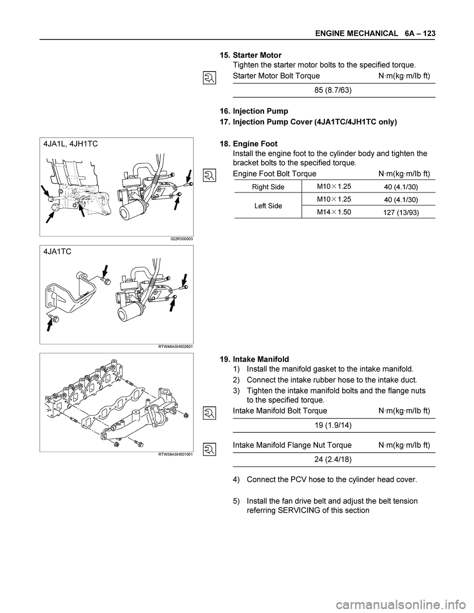
18. Engine Foot
Install the engine foot to the cylinder body and tighten the
bracket bolts to the specified torque.
Engine Foot Bolt Torque N·m(kg·m/Ib ft)
Right Side M10�1.25
40 (4.1/30)
M10�1.25
40 (4.1/30) Left Side
M14�1.50
127 (13/93)
4JA1L, 4JH1TC
022R300003
4JA1TC
RTW46ASH002601
RTW36ASH001001
19. Intake Manifold
1) Install the manifold gasket to the intake manifold.
2) Connect the intake rubber hose to the intake duct.
3) Tighten the intake manifold bolts and the flange nuts
to the specified torque.
Intake Manifold Bolt Torque N·m(kg·m/Ib ft)
19 (1.9/14)
Intake Manifold Flange Nut Torque N·m(kg·m/Ib ft)
24 (2.4/18)
4) Connect the PCV hose to the cylinder head cover.
5) Install the fan drive belt and adjust the belt tension
referring SERVICING of this section
Page 1290 of 4264

6B – 10 ENGINE COOLING
WATER PUMP
REMOVAL AND INSTALLATION
Read this Section carefully before performing any removal and installation procedure. This Section gives you
important points as well as the order of operation. Be sure that you understand everything in this Section before you
begin.
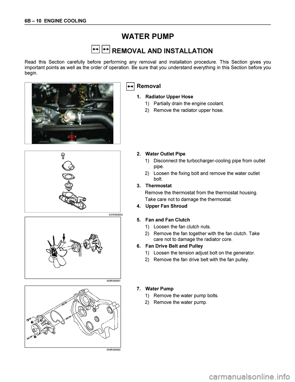
Removal
1. Radiator Upper Hose
1) Partially drain the engine coolant.
2) Remove the radiator upper hose.
031R300003
2. Water Outlet Pipe
1) Disconnect the turbocharger-cooling pipe from outlet pipe.
2) Loosen the fixing bolt and remove the water outlet bolt.
3. Thermostat
Remove the thermostat from the thermostat housing.
Take care not to damage the thermostat.
4. Upper Fan Shroud
5. Fan and Fan Clutch 1) Loosen the fan clutch nuts.
2) Remove the fan together with the fan clutch. Take care not to damage the radiator core.
6. Fan Drive Belt and Pulley
1) Loosen the tension adjust bolt on the generator.
2) Remove the fan drive belt with the fan pulley.
030R300001 7. Water Pump
1) Remove the water pump bolts.
2) Remove the water pump.
030R300002
Page 1291 of 4264

ENGINE COOLING 6B – 11
Inspection and Repair
The water pump is not disassembled type.
Make necessary parts replacement if extreme wear or
damage is found during inspection. Should any of the
following problems occur, the entire water pump assembly
must be replaced.
��Cracks in the water pump body
��Coolant leakage from the seal unit
��Excessive radial play or abnormal noise in the fan center
when rotate by hand
��Excessive thrust play in the fan center (Standard play: less
than 0.2mm)
��Cracks or corrosion in the impeller
Installation
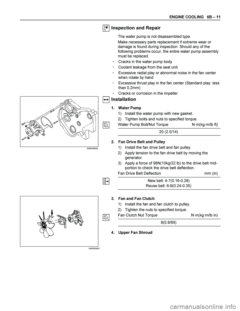
1. Water Pump
1) Install the water pump with new gasket.
2) Tighten bolts and nuts to specified torque.
Water Pump Bolt/Nut Torque N·m(kg·m/lb ft)
20 (2.0/14)
2. Fan Drive Belt and Pulley
1) Install the fan drive belt and fan pulley.
2) Apply tension to the fan drive belt by moving the
generator.
3) Apply a force of 98N(10kg/22 lb) to the drive belt mid-
portion to check the drive belt deflection.
Fan Drive Belt Deflection mm (in)
New belt: 4-7(0.16-0.28)
Reuse belt: 6-9(0.24-0.35)
030R300002
030R300001
3. Fan and Fan Clutch
1) Install the fan and fan clutch to pulley.
2) Tighten the nuts to specified torque.
Fan Clutch Nut Torque N·m(kg·m/lb in)
8(0.8/69)
4. Upper Fan Shroud
Page 1319 of 4264
FUEL SYSTEM 6C – 19
INJECTION PUMP
REMOVAL AND INSTALLATION
Read this Section carefully before performing any removal and installation procedure. This Section gives you
important points as well as the order of operation. Be sure that you understand everything in this Section before you
begin.
Removal
1. Battery
Remove the battery from the battery tray.
6C-1
2. Drive Belt 1) Loosen the adjust bolt of the power steering pump pulley.
2) Remove the drive belt.
3. Power Steering Pump Assembly
P1010003
4. Accelerator Control Cable
Disconnect the accelerator cable from the intake throttle.
5. Vacuum Hose
Disconnect the vacuum hose from the EGR valve and the intake throttle.
6. Fan
Page 1325 of 4264
FUEL SYSTEM 6C – 25
13. Throttle Position Sensor Harness Connector
(4JA1TC/4JH1TC only)
Reconnect the harness connector to the throttle position
sensor.
14. Power Steering Pump Bracket
15. Fan
16. Vacuum Hose
Connect the vacuum hose to the EGR valve and the
intake throttle.
Euro under Euro I Euro II Euro III
4JA1L without with with Not used
4JA1TC Not used Not used Not used With cooler
(EGR cooler)
4JH1TC without with with With
(EGR cooler)
17. Accelerator Control Cable
1) Connect the accelerator cable to the injection pump
(4JA1T) the intake throttle. (4JA1TC/4JH1TC only)
18. Power Steering Pump Assembly
19. Drive Belt
Install the drive belt and adjust the belt tension.
20. Battery
Page 1340 of 4264
6D – 2 ENGINE ELECTRICAL
MAIN DATA AND SPECIFICATIONS
Description
Item
60A 80A
Generator
Type
AC generator with IC regulator and vacuum pump
Hitachi LR160-503E Hitachi LR180-513B
Voltage V
Drive and rotation
Ground polarity 12
V-belt, clockwise viewed from the drive pulley
Negative
Maximum output A 60 80
Engine speed ratio to 1 1.788
Maximum speed rpm 11,000
Weight with vacuum pump kg(lb) 5.8(12.8) 6.4(14.1)
Vacuum Pump
Delivery volume cm3/rev
Exhaust Characteristic
Maximum vacuum
50
-66.7 kPa (-500 mmHg) bulid up time 21 seconds or less at 1,000
rpm
7 seconds or less at 5,000 rpm
-90.7 kPa (-680 mmHg) or more
Starter Motor
Type
Solenoid controlled
Hitachi S13-555
12
2.3
8.76
300 Rated voltage V
Rated output kW
Load characteristics
Terminal voltage V
Load current A
Weight kg(Ib)
4.7 (10.4)
Page 1345 of 4264

ENGINE ELECTRICAL 6D – 7
GENERATOR
REMOVAL AND INSTALLATION
Read this Section carefully before performing any removal and installation procedure. This Section gives you
important points as well as the order of operation. Be sure that you understand everything in this Section before you
begin.
P1010002
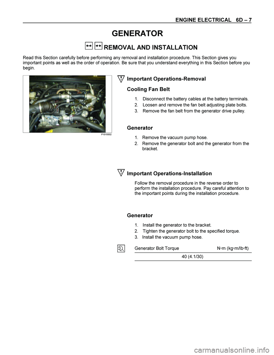
Important Operations-Removal
Cooling Fan Belt
1. Disconnect the battery cables at the battery terminals.
2. Loosen and remove the fan belt adjusting plate bolts.
3. Remove the fan belt from the generator drive pulley.
Generator
1. Remove the vacuum pump hose.
2. Remove the generator bolt and the generator from the bracket.
Important Operations-Installation
Follow the removal procedure in the reverse order to
perform the installation procedure. Pay careful attention to
the important points during the installation procedure.
Generator
1. Install the generator to the bracket.
2. Tighten the generator bolt to the specified torque.
3. Install the vacuum pump hose.
Generator Bolt Torque N �m (kg �m/Ib �ft)
40 (4.1/30)
Page 1346 of 4264
6D – 8 ENGINE ELECTRICAL
033RY00009
Cooling Fan Drive Belt
1. Hold the generator toward the engine.
2. Install the fan belt to the three pulleys.
1 Crankshaft pulley
2 Generator pulley
3 Cooling fan drive pulley
3. Adjust the fan belt tension
Fan belt tension is adjusted by moving the generator.
Depress the drive belt mid-portion with a 98N (10
kg/22 Ib) force.
Cooling Fan Drive Belt Deflection mm (in)
New belt 4 - 7 (0.16 - 0.28)
Reuse belt 6 - 9 (0.24 - 0.35)
4. Tighten the adjusting plate bolts to the specified
torque.
Adjusting Plate Bolt N·m (kg·m/lb·ft)
19 (1.9/14)
5. Reconnect the battery cable to the battery.