2004 ISUZU TF SERIES width
[x] Cancel search: widthPage 2503 of 4264
ENGINE MECHANICAL (C24SE) 6A-83
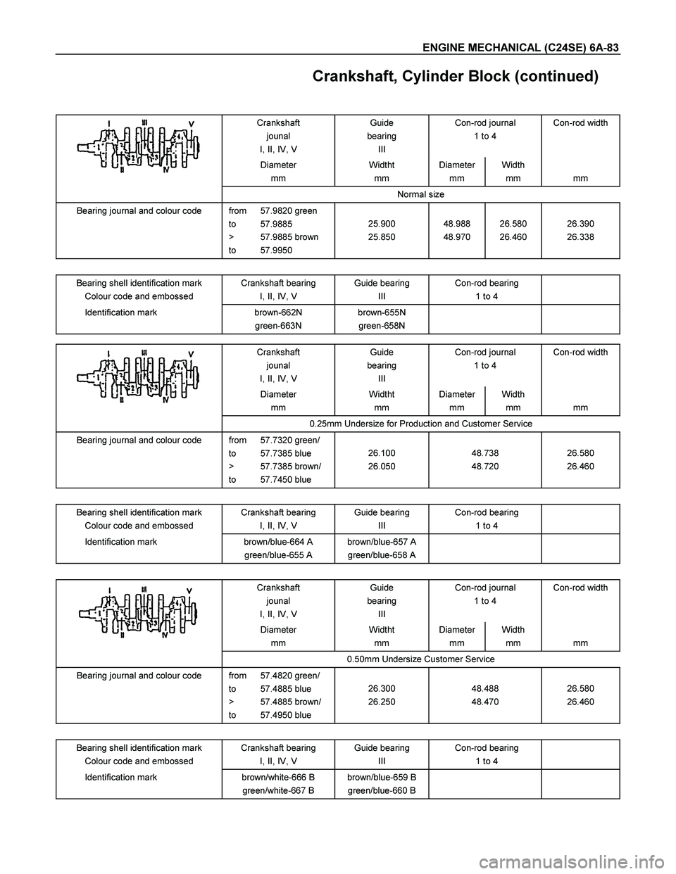
Crankshaft, Cylinder Block (continued)
Crankshaft
jounal
I, II, IV, V Guide
bearing
III Con-rod journal
1 to 4 Con-rod width
Diameter
mm Widtht
mm Diameter
mm Width
mm
mm
Normal size
Bearing journal and colour code from 57.9820 green
to 57.9885
> 57.9885 brown
to 57.9950
25.900
25.850
48.988
48.970
26.580
26.460
26.390
26.338
Bearing shell identification mark
Colour code and embossed Crankshaft bearing
I, II, IV, V Guide bearing
III Con-rod bearing
1 to 4
Identification mark brown-662N
green-663N brown-655N
green-658N
Crankshaft
jounal
I, II, IV, V Guide
bearing
III Con-rod journal
1 to 4 Con-rod width
Diameter
mm Widtht
mm Diameter
mm Width
mm
mm
0.25mm Undersize for Production and Customer Service
Bearing journal and colour code from 57.7320 green/
to 57.7385 blue
> 57.7385 brown/
to 57.7450 blue
26.100
26.050
48.738
48.720
26.580
26.460
Bearing shell identification mark
Colour code and embossed Crankshaft bearing
I, II, IV, V Guide bearing
III Con-rod bearing
1 to 4
Identification mark brown/blue-664 A
green/blue-655 A brown/blue-657 A
green/blue-658 A
Crankshaft
jounal
I, II, IV, V Guide
bearing
III Con-rod journal
1 to 4 Con-rod width
Diameter
mm Widtht
mm Diameter
mm Width
mm
mm
0.50mm Undersize Customer Service
Bearing journal and colour code from 57.4820 green/
to 57.4885 blue
> 57.4885 brown/
to 57.4950 blue
26.300
26.250
48.488
48.470
26.580
26.460
Bearing shell identification mark
Colour code and embossed Crankshaft bearing
I, II, IV, V Guide bearing
III Con-rod bearing
1 to 4
Identification mark brown/white-666 B
green/white-667 B brown/blue-659 B
green/blue-660 B
Page 2505 of 4264
ENGINE MECHANICAL (C24SE) 6A-85
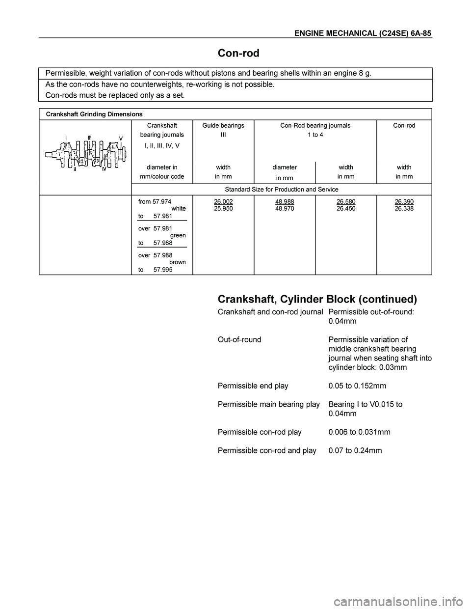
Con-rod
Permissible, weight variation of con-rods without pistons and bearing shells within an engine 8 g.
As the con-rods have no counterweights, re-working is not possible.
Con-rods must be replaced only as a set.
Crankshaft Grinding Dimensions
Crankshaft
bearing journals
I, II, III, IV, V
Guide bearings
III
Con-Rod bearing journals
1 to 4
Con-rod
diameter in
mm/colour code width
in mm diameter
in mm width
in mm width
in mm
Standard Size for Production and Service
from 57.974
white
to 57.981
over 57.981
green
to 57.988
over 57.988
brown
to 57.995 26.002
25.950
48.988
48.970
26.580
26.450
26.390
26.338
Crankshaft, Cylinder Block (continued)
Crankshaft and con-rod journal Permissible out-of-round:
0.04mm
Out-of-round Permissible variation of
middle crankshaft bearing
journal when seating shaft into
cylinder block: 0.03mm
Permissible end play 0.05 to 0.152mm
Permissible main bearing play Bearing I to V0.015 to
0.04mm
Permissible con-rod play 0.006 to 0.031mm
Permissible con-rod and play 0.07 to 0.24mm
Page 2528 of 4264
6C-4 ENGINE FUEL (C24SE)
Fuel Metering
Engine Control Module (ECM) is in complete control of this fuel
delivery system during normal driving conditions.
The intake manifold function, like that of a diesel, is used only
to let air into the engine. The fuel is injected by separate
injectors that are mounted over the intake manifold.
The Manifold Absolute Pressure (MAP) sensor measures the
changes in the intake manifold pressure which result from
engine load and speed changes, which the MAP senso
r
converts to a voltage output.
This sensor generates the voltage to change corresponding to
the flow of the air drawn into the engine.
The changing voltage is transformed into an electric signal and
provided to the ECM.
With receipt of the signals sent from the MAP sensor, Intake
Air Temperature sensor and others, the ECM determines an
appropriate fuel injection pulse width feeding such information
to the fuel injector valves to effect an appropriate air/fuel ratio.
The Multiport Fuel Injection system utilizes an injection system
where the injectors turn on at every crankshaft revolution. The
ECM controls the injector on time so that the correct amount o
f
fuel is metered depending on driving conditions.
Two interchangeable "O" rings are used on the injector tha
t
must be replaced when the injectors are removed.
The fuel rail is attached to the top of the intake manifold and
supplies fuel to all the injectors.
Fuel is recirculated through the rail continually while the engine
is running. This removes air and vapors from the fuel as well
as keeping the fuel cool during hot weather operation.
The fuel pressure control valve that is mounted on the fuel rail
maintains a pressure differential across the injectors under all
operating conditions. It is accomplished by controlling the
amount of fuel that is recirculated back to the fuel tank based
on engine demand.
See Section "Driveability and Emission" for more information
and diagnosis.
Page 2627 of 4264
ENGINE DRIVEABILITY AND EMISSIONS 6E–51
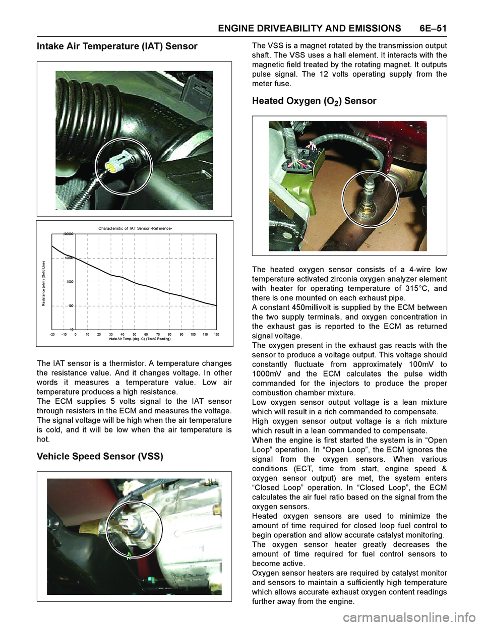
Intake Air Temperature (IAT) Sensor
The IAT sensor is a thermistor. A temperature changes
the resistance value. And it changes voltage. In other
words it measures a temperature value. Low air
temperature produces a high resistance.
The ECM supplies 5 volts signal to the IAT sensor
through resisters in the ECM and measures the voltage.
The signal voltage will be high when the air temperature
is cold, and it will be low when the air temperature is
hot.
Vehicle Speed Sensor (VSS)
The VSS is a magnet rotated by the transmission output
shaft. The VSS uses a hall element. It interacts with the
magnetic field treated by the rotating magnet. It outputs
pulse signal. The 12 volts operating supply from the
meter fuse.
Heated Oxygen (O2) Sensor
The heated ox ygen sensor consists of a 4-wire low
temperature activated zirconia ox ygen analyzer element
with heater for operating temperature of 315°C, and
there is one mounted on each ex haust pipe.
A constant 450millivolt is supplied by the ECM between
the two supply terminals, and oxygen concentration in
the ex haust gas is reported to the ECM as returned
signal voltage.
The ox ygen present in the ex haust gas reacts with the
sensor to produce a voltage output. This voltage should
constantly fluctuate from approx imately 100mV to
1000mV and the ECM calculates the pulse width
commanded for the injectors to produce the proper
combustion chamber mix ture.
Low ox ygen sensor output voltage is a lean mix ture
which will result in a rich commanded to compensate.
High ox ygen sensor output voltage is a rich mix ture
which result in a lean commanded to compensate.
When the engine is first started the system is in “Open
Loop” operation. In “Open Loop”, the ECM ignores the
signal from the ox ygen sensors. When various
conditions (ECT, time from start, engine speed &
ox ygen sensor output) are met, the system enters
“Closed Loop” operation. In “Closed Loop”, the ECM
calculates the air fuel ratio based on the signal from the
ox ygen sensors.
Heated ox ygen sensors are used to minimize the
amount of time required for closed loop fuel control to
begin operation and allow accurate catalyst monitoring.
The ox ygen sensor heater greatly decreases the
amount of time required for fuel control sensors to
become active.
Oxygen sensor heaters are required by catalyst monitor
and sensors to maintain a sufficiently high temperature
which allows accurate ex haust ox ygen content readings
further away from the engine.
C haract erist ic of I A T Sen sor -Ref erence-
10 100 1000 10000 100000
- 20 - 10 0 10 20 30 40 50 60 70 80 90 100 110 120
I nt ake A i r T emp. ( deg . C ) ( Tec h2 R eadi ng )
Resistance (ohm) (Solid Line)
Page 2633 of 4264
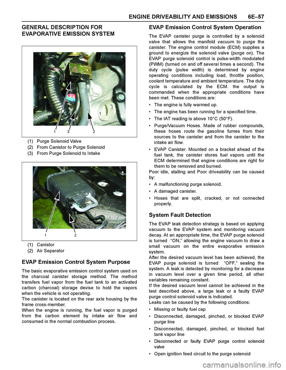
ENGINE DRIVEABILITY AND EMISSIONS 6E–57
GENERAL DESCRIPTION FOR
EVAPORATIVE EMISSION SYSTEM
EVAP Emission Control System Purpose
The basic evaporative emission control system used on
the charcoal canister storage method. The method
transfers fuel vapor from the fuel tank to an activated
carbon (charcoal) storage devise to hold the vapors
when the vehicle is not operating.
The canister is located on the rear ax le housing by the
frame cross-member.
When the engine is running, the fuel vapor is purged
from the carbon element by intake air flow and
consumed in the normal combustion process.
EVAP Emission Control System Operation
The EVAP canister purge is controlled by a solenoid
valve that allows the manifold vacuum to purge the
canister. The engine control module (ECM) supplies a
ground to energize the solenoid valve (purge on). The
EVAP purge solenoid control is pulse-width modulated
(PWM) (turned on and off several times a second). The
duty cycle (pulse width) is determined by engine
operating conditions including load, throttle position,
coolant temperature and ambient temperature. The duty
cycle is calculated by the ECM. the output is
commanded when the appropriate conditions have
been met. These conditions are:
The engine is fully warmed up.
The engine has been running for a specified time.
The IAT reading is above 10°C (50°F).
Purge/Vacuum Hoses. Made of rubber compounds,
these hoses route the gasoline fumes from their
sources to the canister and from the canister to the
intake air flow.
EVAP Canister. Mounted on a bracket ahead of the
fuel tank, the canister stores fuel vapors until the
ECM determined that engine conditions are right for
them to be removed and burned.
Poor idle, stalling and Poor driveability can be caused
by:
A malfunctioning purge solenoid.
A damaged canister.
Hoses that are split, cracked, or not connected
properly.
System Fault Detection
The EVAP leak detection strategy is based on applying
vacuum to the EVAP system and monitoring vacuum
decay. At an appropriate time, the EVAP purge solenoid
is turned “ON,” allowing the engine vacuum to draw a
small vacuum on the entire evaporative emission
system.
After the desired vacuum level has been achieved, the
EVAP purge solenoid is turned “OFF,” sealing the
system. A leak is detected by monitoring for a decrease
in vacuum level over a given time period, all other
variables remaining constant.
If the desired vacuum level cannot be achieved in the
test described above, a large leak or a faulty EVAP
purge control solenoid valve is indicated.
Leaks can be caused by the following conditions:
Missing or faulty fuel cap
Disconnected, damaged, pinched, or blocked EVAP
purge line
Disconnected, damaged, pinched, or blocked fuel
tank vapor line
Disconnected or faulty EVAP purge control solenoid
valve
Open ignition feed circuit to the purge solenoid (1) Purge Solenoid Valve
(2) From Canistor to Purge Solenoid
(3) From Purge Solenoid to Intake
(1) Canistor
(2) Air Separator
132
12
Page 2634 of 4264
6E–58 ENGINE DRIVEABILITY AND EMISSIONS
Damaged EVAP canister
Leaking fuel sender assembly O-ring
Leaking fuel tank or fuel filler neck
The ECM supplies a ground to energize the purge
control solenoid valve (purge “ON” ). The EVAP purge
control is turned “ON” and “OFF,” several times a
second. The duty cycle (pulse width) is determined by
engine operating conditions including load, throttle
position, coolant temperature and ambient temperature.
The duty cycle is calculated by the ECM and the output
is commanded when the appropriate conditions have
been met.
The system checks for conditions that cause the EVAP
system to purge continuously by commanding the EVAP
purge solenoid “OFF”, EVAP purge solenoid duty ratio
“0%”. If fuel tank vacuum level increases during the test,
a continuous purge flow condition is indicated. This can
be caused by the following conditions:
EVAP purge solenoid leaking
EVAP purge and engine vacuum lines switched at the
EVAP purge control solenoid valve
EVAP purge control solenoid valve driver circuit
grounded
Page 2648 of 4264
6E–72 ENGINE DRIVEABILITY AND EMISSIONS
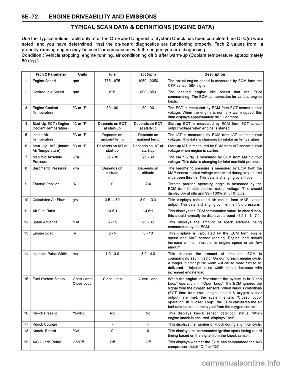
TYPICAL SCAN DATA & DEFINITIONS (ENGINE DATA)
Use the Typical Values Table only after the On-Board Diagnostic System Check has been completed, no DTC(s) were
noted, and you have determined that the on-board diagnostics are functioning properly. Tech 2 values from a
properly-running engine may be used for comparison with the engine you are diagnosing.
Condition : Vehicle stopping, engine running, air conditioning off & after warm-up (Coolant temperature approx imately
80 deg.)
Tech 2 ParameterUnitsIdle2000rpmDescription
1 Engine Speed rpm775 - 8751950 - 2050 The actual engine speed is measured by ECM from the
CKP sensor 58X signal.
2 Desired Idle Speed rpm825800 - 850 The desired engine idle speed that the ECM
commanding. The ECM compensates for various engine
loa ds.
3 Engine Coolant
Te mpe rature°C or °F80 - 9080 - 90 The ECT is measured by ECM from ECT sensor output
voltage. When the engine is normally warm upped, this
data displays approximately 80 °C or more.
4 Sta rt Up ECT (Engine
Coolant Temperature)°C or °FDepends on ECT
a t start-upDepends on ECT
at sta rt-upStart-up ECT is measured by ECM from ECT sensor
output voltage when engine is started.
5Inta ke Air
Temperature °C or °FDe pe nds on
ambient tempDepends on
ambient tempThe IAT is mea sure d by ECM from IAT sensor o utput
voltage. This data is changing by intake air temperature.
6 Sta rt Up IAT (Inta ke
Air Temperature)°C or °FDepends on IAT at
sta rt-upDepends on IAT at
start-upStart-up IAT is me asured by ECM fro m IAT se nso r o utput
voltage when engine is started.
7 Manifold Absolute
Pre ssurekPa31 - 3625 - 30The MAP (kPa ) is me asure d by ECM fro m MAP o utput
voltage. This data is changing by inlet manifold pressure.
8 Barometric Pressure kPaDe pe nds on
altitudeDepends on
altitudeThe ba rome tric pre ssure is me asured by ECM fro m the
MAP sensor output voltage monitored during key up and
w ide o pe n thro ttle. This data is cha nging by a ltitude.
9 Throttle Position %02-4 Throttle position operating angle is measured by the
ECM from throttle position output voltage. This should
displa y 0% at idle a nd 99 - 100% at full throttle .
10 Calculated Air Flow g/s3.5 -4.508.0 - 10.0 This displays calculated air mount from MAP sensor
output. This data is changing by inlet manifold pressure .
11 Air Fuel Ratio14.6:114.6:1 This displays the ECM commanded value. In closed loop,
this should normally be displayed around 14.2:1 - 14.7:1.
12 Spark Advance °CA8 - 1525 - 32 This displays the amount of spark advance being
commanded by the ECM.
13 Engine Load %2 - 55 - 10 This displays is calculated by the ECM form engine
speed and MAF sensor reading. Engine load should
incre ase with an incre ase in engine spe ed or air flo w
amount.
14 Injection Pulse Width ms1.0 - 3.0 3.0 - 4.0 This displays the amount of time the ECM is
commanding each injector On during each engine cycle.
A lo nger injecto r pulse width will ca use more fuel to be
delivered. Injector pulse width should increase with
increased engine load.
15 Fuel System Status Open Loop/
Close LoopClo se Loo pClose Loop When the engine is first started the system is in “Open
Loop” operation. In “Open Loop”, the ECM ignores the
signal from the oxygen sensors. When various conditions
(ECT, time from start, engine speed & oxygen sensor
o utput) are me t, the syste m e nte rs “Closed Lo op”
o pera tio n. In “Close d Lo o p”, the ECM ca lculate s the air
fuel ratio based on the signal from the oxygen sensors.
16 Knock Present Yes/NoNoNo This displays knock sensor detection status. When
engine knock is occurred, displays "Yes".
17 Knock Counter-- This displays the number of knock during a ignition cycle.
18 Kno ck Reta rd °CA00 This displa ys the commande d ignitio n spa rk timing re tard
timing based on the signal from the knock sensor.
19 A/C Clutch Re la y On/OffOffOff This display s whe the r the ECM has co mma nde d the A/C
co mpre ssor clutch “On” or “Off”.
Page 2651 of 4264
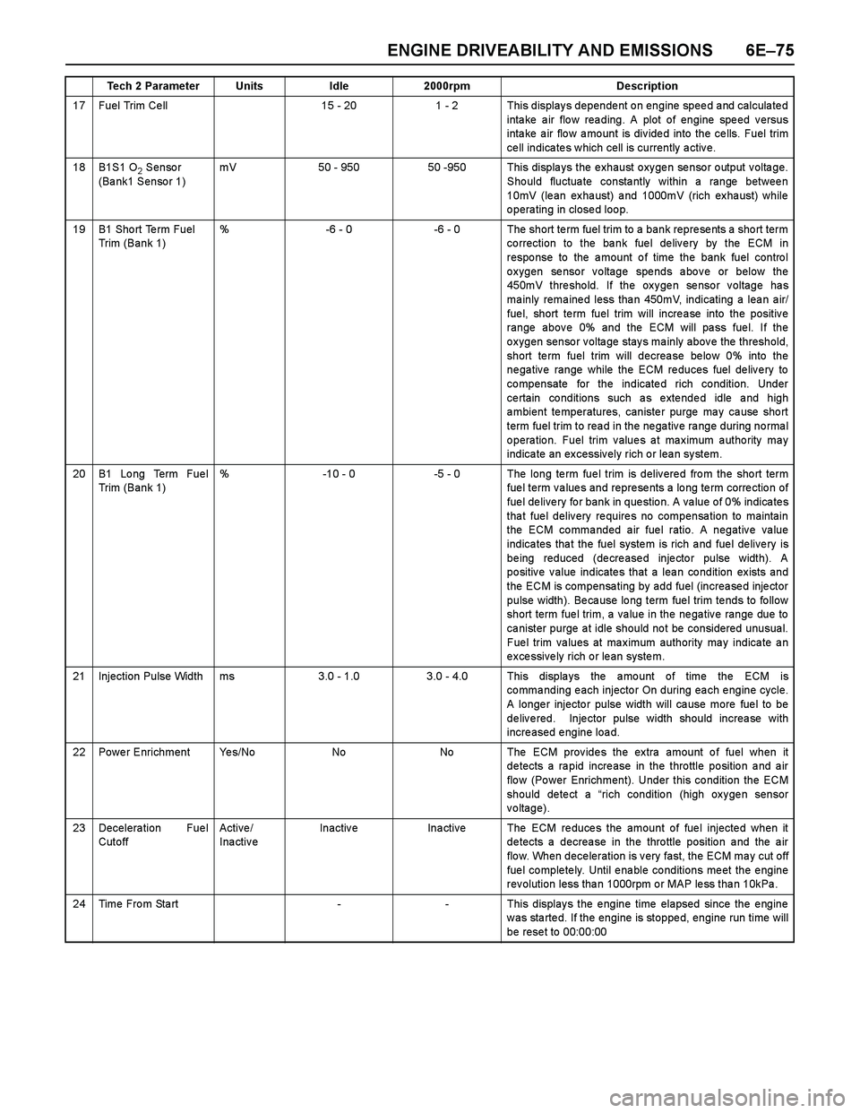
ENGINE DRIVEABILITY AND EMISSIONS 6E–75
17 Fuel Trim Ce ll15 - 201 - 2 This displays dependent on engine speed and calculated
intake air flow reading. A plot of engine speed versus
inta ke a ir flo w a mo unt is div ide d into the ce lls. Fuel trim
ce ll indica te s w hich cell is currently a ctiv e.
18B1S1 O2 Sensor
(Bank1 Sensor 1)mV50 - 95050 -950 This displays the exhaust oxygen sensor output voltage.
Should fluctuate constantly within a range between
10mV (lean exhaust) and 1000mV (rich exhaust) while
operating in closed loop.
19B1 Sho rt Te rm Fuel
Trim (Bank 1)%-6 - 0-6 - 0 The short term fuel trim to a bank represents a short term
co rrection to the ba nk fue l de liv e ry by the ECM in
response to the amount of time the bank fuel control
oxygen sensor voltage spends above or below the
450mV threshold. If the oxygen sensor voltage has
ma inly rema ine d less tha n 450mV, indicating a lea n a ir/
fue l, short te rm fuel trim will incre a se into the positiv e
range above 0% and the ECM will pass fuel. If the
oxygen sensor voltage stays mainly above the threshold,
short term fuel trim will decrease below 0% into the
negative range while the ECM reduces fuel delivery to
compensate for the indicated rich condition. Under
ce rtain co nditions such a s e xte nde d idle a nd high
ambient temperatures, canister purge may cause short
term fuel trim to rea d in the ne ga tiv e ra nge during no rma l
operation. Fuel trim values at maximum authority may
indica te an ex cessiv ely rich o r lea n sy stem.
20B1 Lo ng Term Fue l
Trim (Bank 1)%-10 - 0-5 - 0 The long te rm fue l trim is deliv ere d fro m the sho rt term
fuel term values and represents a long term correction of
fuel delivery for bank in question. A value of 0% indicates
that fuel delivery requires no compensation to maintain
the ECM commanded air fuel ratio. A negative value
indica tes tha t the fuel syste m is rich a nd fue l de live ry is
being reduced (decreased injector pulse width). A
positive value indicates that a lean condition exists and
the ECM is compensating by add fuel (increased injector
pulse width). Be ca use lo ng term fue l trim te nds to fo llow
short term fuel trim, a value in the negative range due to
canister purge at idle should not be considered unusual.
Fuel trim values at maximum authority may indicate an
excessively rich or lean system.
21Injection Pulse Widthms3.0 - 1.03.0 - 4.0 This displays the amount of time the ECM is
co mma nding e ach injecto r On during ea ch e ngine cycle.
A longer injector pulse width will cause more fuel to be
delivered. Injector pulse width should increase with
increased engine load.
22Power EnrichmentYe s / N oNoNo The ECM provides the extra amount of fuel when it
detects a rapid increase in the throttle position and air
flo w (Po wer Enrichment). Under this co ndition the ECM
should detect a “rich condition (high oxygen sensor
voltage).
23Decelera tion Fue l
Cut o ff Active /
InactiveInactiveIna ctiveThe ECM reduces the amount of fuel injected when it
detects a decrease in the throttle position and the air
flow. When deceleration is very fast, the ECM may cut off
fue l co mple te ly. Until e na ble co nditions me et the e ngine
rev olution less tha n 1000rpm o r MAP le ss tha n 10kPa .
24Time From Start--This displays the engine time elapsed since the engine
w as sta rte d. If the engine is stoppe d, engine run time will
be rese t to 00:00:00
Tech 2 ParameterUnitsIdle2000rpmDescription