Page 3900 of 4264
7A4–92 UNIT REPAIR (AW30–40LE)
Transmission Valve Body assembly
Disassembled View
2 40R20 0039
E nd O FCallo ut
Legend
(1) Detent spring
(2) Manual shift valve
(3) Upper valve body
(4) No.1 gasket (Upper valve body side)(5) Valve body plate
(6) Clamp
(7) Pressure control solenoid
(8) No.2 gasket (Lower valve body side)
(9) Lower valve body
Page 3929 of 4264
UNIT REPAIR (AW30–40LE) 7A4–121
Transmission Case
Disassembled View
24 9RY 0 0001
E nd O FCallo ut
Disassembly
1. Using a chisel, cut off the spacer and remove it from
the shaft.
24 9RY 0 0002
Legend
(1) Spacer
(2) Pin
(3) Manual valve lever shaft(4) Manual valve lever
(5) Oil seal
(6) Oil seal
Page 3930 of 4264
7A4–122 UNIT REPAIR (AW30–40LE)
2. Using a punch, drive out the pin.
24 9RY 0 000 3
3. Pull the manual valve lever shaft out through the
case by the threads.
4. Take out the manual valve lever.
5. Using a screwdriver, remove the oil seals.
24 9RY 0 000 4
Reassembly
1. Coat a new oil seal lip with multi purpose grease.
Using special tool, drive in the oil seal.
Oil seal installer : J–37232–2
RTW3 7A SH00 0701
2. Assemble a new spacer to the manual valve lever.
3. Install the manual valve lever shaft to the
transmission case through the manual valve lever
by the threads.
24 9RY 0 0005
Page 3945 of 4264
WORKSHOP MANUAL
TF SERIES
TRANSMISSION
JR405E MODEL
SECTION 7A
Page 3947 of 4264

CONSTRUCTION AND FUNCTION 7A1-1
SECTION 7A1
CONSTRUCTION AND FUNCTION
TABLE OF CONTENTS
PAGE
DESCRIPTION ..............................................................................................................................7A1- 3
CONSTRUCTION ....................................................................................................................7A1- 3
MAIN DATA AND SPECIFICATION .....................................................................................7A1- 4
NUMBER PLATE LOCATION ...............................................................................................7A1- 5
ELECTRONIC CONTROL COMPONENTS LOCATION ..................................................7A1- 6
TRANSMISSION CONTROL UNIT (TCM) PERIPHERAL CIRCUIT ..............................7A1- 7
STRUCTURE AND FUNCTION OF COMPONENT ...........................................................7A1- 8
TORQUE CONVERTER (WITH LOCK-UP FUNCTION) ..................................................7A1- 8
OIL PUMP .................................................................................................................................7A1- 9
INPUT SHAFT ..........................................................................................................................7A1- 10
OUTPUT SHAFT ......................................................................................................................7A1- 10
GEAR SHIFTING MECHANISM ............................................................................................7A1- 10
CONTROL VALVE ...................................................................................................................7A1- 14
OIL PASSAGE .........................................................................................................................7A1- 19
PARKING FUNCTION .............................................................................................................7A1- 20
INHIBITOR SWITCH ...............................................................................................................7A1- 21
TURBINE SENSOR .................................................................................................................7A1- 22
SPEED SENSOR .....................................................................................................................7A1- 22
THROTTLE POSITION SENSOR (TPS) .............................................................................7A1- 23
ENGINE SPEED SENSOR (=TDC SENSOR) ....................................................................7A1- 23
BRAKE SWITCH ......................................................................................................................7A1- 24
MODE SELECT SWITCH .......................................................................................................7A1- 24
TRANSMISSION CONTROL MODULE (TCM) ..................................................................7A1- 25
CONTROL MECHANISM ............................................................................................................7A1- 26
CONTENT OF FUNCTION AND CONTROL ......................................................................7A1- 26
CONTROL ITEM, INPUT AND OUTPUT .................................................................... 7A1- 29
LINE PRESSURE CONTROL ..................................................................................... 7A1- 30
Page 3948 of 4264

7A1-2 CONSTRUCTION AND FUNCTION
PAGE
LOCK-UP CONTROL ..............................................................................................................7A1- 30
DIRECT ELECTRIC SHIFT CONTROL (DESC) ................................................................7A1- 31
LEARNING CONTROL ............................................................................................... 7A1- 33
MAJOR INPUT/OUTPUT COMPONENT AND THEIR FUNCTIONS .......................... 7A1- 34
CONTROL CIRCUIT BLOCK DIAGRAM .................................................................... 7A1- 35
GEAR TRAIN (TRANSMISSION MECHANISM) OPERATION AND
HYDRAULIC CIRCUIT ................................................................................................. 7A1- 36
CONSTRUCTION AND OPERATION ......................................................................... 7A1- 36
COMPONENT NAME AND FUNCTION ...................................................................... 7A1- 36
COMPONENT AND THEIR OPERATING CONDITION ............................................. 7A1- 37
Page 3949 of 4264

CONSTRUCTION AND FUNCTION 7A1-3
DESCRIPTION
CONSTRUCTION
1 Converter Housing 6 Low Clutch 11 Oil Pump
2 Torque Converter 7 Low & Reverse Brake 12 Control Valve
3 High Clutch 8 Output Shaft 13 Low One-way Clutch
4 Reverse Clutch 9 Extension Housing 14 Parking Gear
5 2-4 Brake 10 Input Shaft
Figure 1. Construction of Automatic Transmission
The JR405E automatic transmission is electrically controlled by a microcomputer transmission control module
(TCM). There are four forward speeds and one reverse speed.
This JR405E automatic transmission employs a clutch pressure direct control system (Direct Electronic Shift
Control: DESC) using a duty cycle type solenoid, which ensures high shift quality.
This transmission also controls learning and constantly checks the time of each clutch and brake required for
the speed change to match this time with the target value for the optimum speed change.
The TCM will automatically select the most appropriate shift points and lock-up points depending on the
throttle opening angle, the vehicle speed and the vehicle load.
If any trouble arises in the vehicle sensor, throttle sensor, solenoid, etc., the fail-safe control function is
activated to keep the running performance.
Problems with the sensors, the solenoids can be quickly detected with the self diagnosis procedure described
in this manual.
The JR405E automatic transmission consists of the torque converter, the oil pump, the input shaft, the out put
shaft, the planetary gears and the control valve.
The gear train consists of two planetary gear sets and three multiple plate clutches in combination with two
multiple plate brakes and a one-way clutch.
2WD
4WD
Page 3951 of 4264
CONSTRUCTION AND FUNCTION 7A1-5
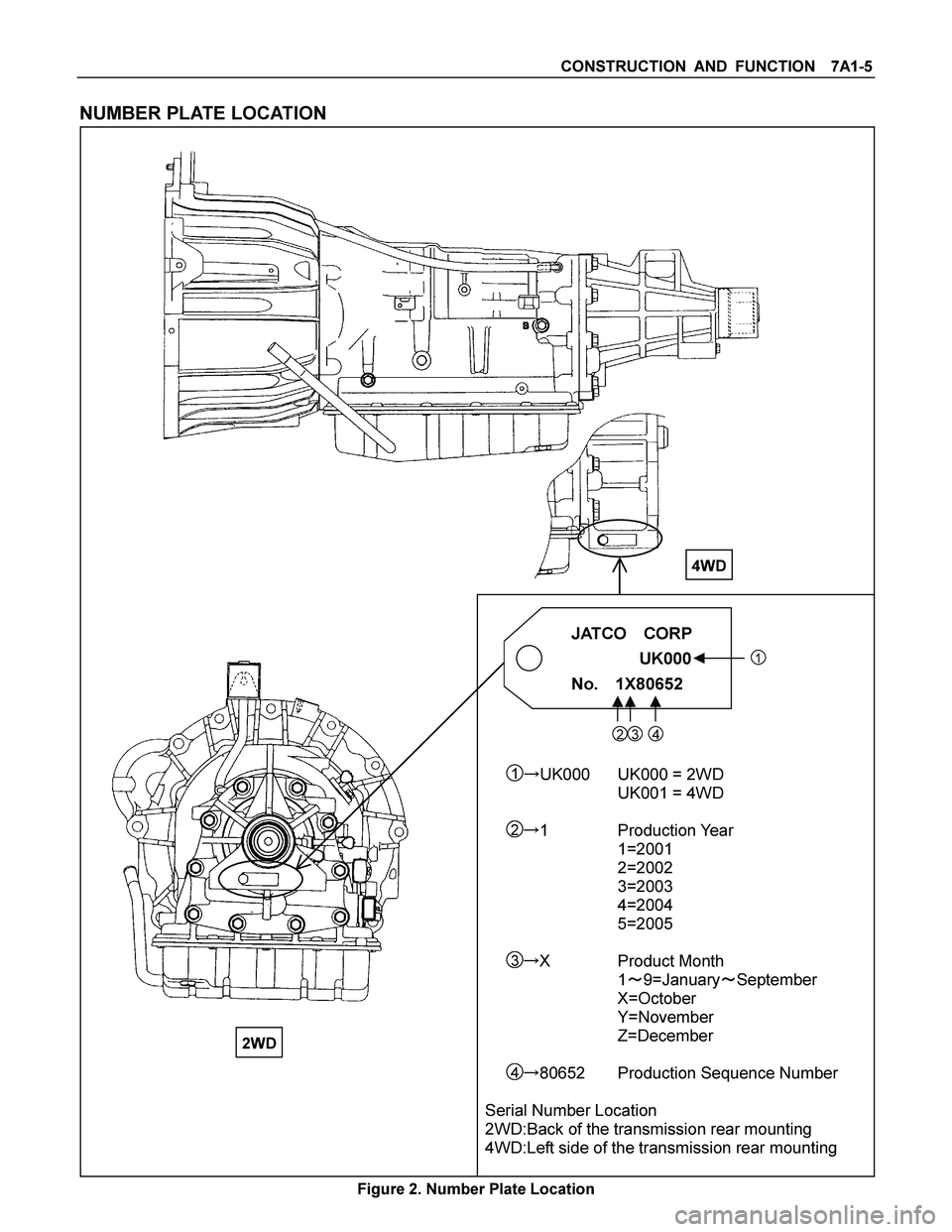
NUMBER PLATE LOCATION
JATCO CORP
���
������ ��� UK000�
�� �
���
������ ���1
No. 1X80652����
�������� ����
23 4
1�UK000 UK000 = 2WD
UK001 = 4WD
2�1 Production Year
1=2001
2=2002
3=2003
4=2004
5=2005
3�X Product Month
1�9=January�September
X=October
Y=November
Z=December
4�80652 Production Sequence Number
Serial Number Location
2WD:Back of the transmission rear mounting
4WD:Left side of the transmission rear mounting
Figure 2. Number Plate Location
4WD
2WD

Transmission Valve Body assembly
Disassembled View
2 40R20 0039
E nd O FCallo ut
Legend
(1) Detent spring
(2) Manual shift valve
(3) Upper valve body
(4) No.1 gasket")
 7A4–121
Transmission Case
Disassembled View
24 9RY 0 0001
E nd O FCallo ut
Disassembly
1. Using a chisel, cut off the spacer and remove it from
the shaft.
24 9RY 0 0002
Leg")

2. Using a punch, drive out the pin.
24 9RY 0 000 3
3. Pull the manual valve lever shaft out through the
case by the threads.
4. Take out the manual valve lever.
5.")