Page 4014 of 4264

6. If you select “continue”, you have to select “Model Year”, “Vehicle Type”.
7. After that, push button and turn Ignition switch tuned on, off, on foll")
7A2-22 DIAGNOSIS (JR405E)
6. If you select “continue”, you have to select “Model Year”, “Vehicle Type”.
7. After that, push button and turn Ignition switch tuned on, off, on following Tech-2 display. Tech-2 will read
information from controller after this procedure.
8. During obtaining information, Tech-2 is receiving information from the control unit ECM and TCM at the same
time. With VIN not being programmed into the new control unit at the time of shipment, "obtaining
information" is not complete (because the vehicle model, engine model and model year are specified from
VIN). For the procedure get additional information on vehicles, instruction will be provided in dialog form,
when TIS2000 is in operation.
9. Following instructions by Tech-2, push the "Exit" switch of Tech-2, turn off the ignition of the vehicle and turn
off the power of Tech-2, thereby removing from the vehicle.
3. Data Exchange
1. Connect Tech-2 to P/C, turn on the power and click the "Next" button of P/C.
2. Check VIN of the vehicle and choose "Next".
3. Select “Transmission” in the “System Type” selection.
4. When a lack of data is asked from among the following menu, enter accordingly.
Select following Menu
� Model Year
� Model
� Engine type
� Destination code (vehicles for general export)*1
* 1: How to read the destination code:
Destination code can be read from service ID Plate affixed on vehicle, while on service ID Plate the destination
code is described at the right-hand edge of Body Type line. In the figure, the destination code can be read as "RR3"
for Australia.
Page 4069 of 4264
 7A2-77
Step Action Yes No
6 Is the quantity of ATF correct?
Go to Step 7
Correct the quantity of
ATF.
Go to Step 9
7 Connect the Tech 2 and test the solenoids of respective")
DIAGNOSIS (JR405E) 7A2-77
Step Action Yes No
6 Is the quantity of ATF correct?
Go to Step 7
Correct the quantity of
ATF.
Go to Step 9
7 Connect the Tech 2 and test the solenoids of respective
solenoids for low & reverse brake, 2-4 brake, high clutch and
low clutch. Is operation sound heard from each solenoid?
Go to Step 8
Replace the solenoid
that does not generate
the operation sound.
Go to Step 9
8 Check the line pressure during the idling and at the engine stall
speed. Is the line pressure correct?
Go to Step 10
Either control valve, oil
pump or power train
parts (clutch, brake)
will be faulty. Replace
or overhaul the
transmission unit.
Go to step 10
9 Run the vehicle, and is the gear shifted from 1st to 4th
correctly?
Go to Step 10
Either control valve, oil
pump or power train
parts (clutch, brake)
will be faulty. Replace
or overhaul the
transmission unit.
Go to step 10
10 Clear the DTC from the memory and perform the work after
repair. Is the same DTC code outputted again in the
subsequent DTC check?
Replace the TCM Go to Step 11
11 Are the other DTCs outputted?
Go to Other DTC
Section Action is completed
Page 4154 of 4264

DESCRIPTION
Before performing on-vehicle service on the automatic
transmission, check that the engine idling speed and
general engine condition are normal.")
7A3-2 ON-VEHICLE SERVICE (JR405E)
DESCRIPTION
Before performing on-vehicle service on the automatic
transmission, check that the engine idling speed and
general engine condition are normal.
AUTOMATIC TRANSMISSION FLUID (ATF)
Inspect
Remove the transmission dipstick to check the condition
of the ATF.
Clean the dipstick and look for gum or varnish.
Gum or varnish indicate scorching of the clutch band
and other parts.
The transmission control module, the transmission unit,
and the vehicle must be carefully checked if gum or
varnish is present.
ATF LEVEL
Inspect
Hot Level
1. Warm up the engine and the transmission by driving
the vehicle on the road so that the temperature
reaches around 80�C (176�F).
Do not turn the engine off.
2. Park the vehicle on a level surface.
3. Apply the parking brake firmly.
4. Let the engine run at idle.
Move the select lever slowly through all the gea
r
ranges.
Stop in each gear range just long enough for the
transmission to engage.
5. Return the select lever to either “P” or “N”.
C07RW009
6. Remove the ATF level dipstick.
7. Wipe the dipstick clean with a paper towel.
8. Reinsert the dipstick and wait several seconds.
9. Remove the dipstick.
The ATF level should be inside the “H” range on the
dipstick.
242R300001
If the ATF level is below the “H” range, ATF must be
added.
Page 4175 of 4264
 7A4-1
SECTION 7A4
UNIT REPAIR (JR405E)
TABLE OF CONTENTS
PAGE
Automatic Transmission Disassembly ..................................................................... 7A4")
UNIT REPAIR (JR405E) 7A4-1
SECTION 7A4
UNIT REPAIR (JR405E)
TABLE OF CONTENTS
PAGE
Automatic Transmission Disassembly ..................................................................... 7A4 - 2
Control Valve Assembly ............................................................................................ 7A4 - 11
Control Valve Upper Body ........................................................................................ 7A4 - 18
Control Valve Lower Body ........................................................................................ 7A4 - 23
Oil Pump Assembly ................................................................................................... 7A4 - 28
Clutch Pack (Reverse and High Clutch Assembly) ................................................. 7A4 - 33
Carrier and Low Clutch Assembly ........................................................................... 7A4 - 41
Transmission Case .................................................................................................... 7A4 - 54
Bearing and Bearing Race Installation Position ..................................................... 7A4 - 66
Automatic Transmission Reassembly ..................................................................... 7A4 - 69
Service Standard ....................................................................................................... 7A4 - 83
Special Service Tool .................................................................................................. 7A4 - 85
Page 4255 of 4264
UNIT REPAIR (JR405E) 7A4-81
43ASSY119
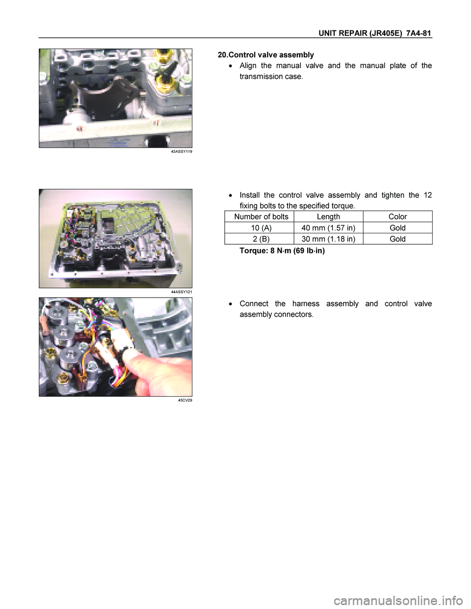
20.Control valve assembly
�
Align the manual valve and the manual plate of the
transmission case.
� Install the control valve assembly and tighten the 12
fixing bolts to the specified torque.
Number of bolts Length Color
10 (A) 40 mm (1.57 in) Gold
2 (B) 30 mm (1.18 in) Gold
44ASSY121
Torque: 8 N �
��
�
m (69 Ib �
��
�
in)
45CV29
�
Connect the harness assembly and control valve
assembly connectors.