Page 3809 of 4264

UNIT REPAIR (AW30–40LE) 7A4–1
TRANSMISSION
CONTENTS
UNIT REPAIR (AW30–40LE)
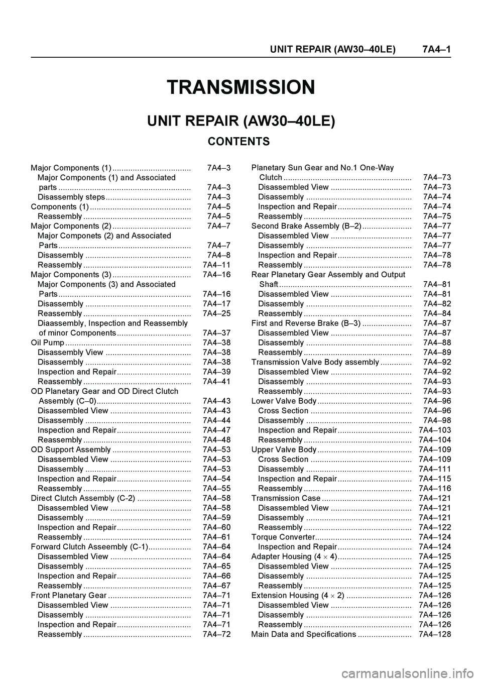
Major Components (1) ................................... 7A4–3
Major Components (1) and Associated
parts ........................................................... 7A4–3
Disassembly steps...................................... 7A4–3
Components (1) ............................................. 7A4–5
Reassembly ................................................ 7A4–5
Major Components (2) ................................... 7A4–7
Major Componets (2) and Associated
Parts ........................................................... 7A4–7
Disassembly ............................................... 7A4–8
Reassembly ................................................ 7A4–11
Major Components (3) ................................... 7A4–16
Major Components (3) and Associated
Parts ........................................................... 7A4–16
Disassembly ............................................... 7A4–17
Reassembly ................................................ 7A4–25
Diaassembly, Inspection and Reassembly
of minor Components ................................. 7A4–37
Oil Pump ........................................................ 7A4–38
Disassembly View ...................................... 7A4–38
Disassembly ............................................... 7A4–38
Inspection and Repair................................. 7A4–39
Reassembly ................................................ 7A4–41
OD Planetary Gear and OD Direct Clutch
Assembly (C–0).......................................... 7A4–43
Disassembled View .................................... 7A4–43
Disassembly ............................................... 7A4–44
Inspection and Repair................................. 7A4–47
Reassembly ................................................ 7A4–48
OD Support Assembly ................................... 7A4–53
Disassembled View .................................... 7A4–53
Disassembly ............................................... 7A4–53
Inspection and Repair................................. 7A4–54
Reassembly ................................................ 7A4–55
Direct Clutch Assembly (C-2) ........................ 7A4–58
Disassembled View .................................... 7A4–58
Disassembly ............................................... 7A4–59
Inspection and Repair................................. 7A4–60
Reassembly ................................................ 7A4–61
Forward Clutch Asseembly (C-1)................... 7A4–64
Disassembled View .................................... 7A4–64
Disassembly ............................................... 7A4–65
Inspection and Repair................................. 7A4–66
Reassembly ................................................ 7A4–67
Front Planetary Gear ..................................... 7A4–71
Disassembled View .................................... 7A4–71
Disassembly ............................................... 7A4–71
Inspection and Repair................................. 7A4–71
Reassembly ................................................ 7A4–72Planetary Sun Gear and No.1 One-Way
Clutch ......................................................... 7A4–73
Disassembled View .................................... 7A4–73
Disassembly ............................................... 7A4–74
Inspection and Repair ................................. 7A4–74
Reassembly ................................................ 7A4–75
Second Brake Assembly (B–2)...................... 7A4–77
Disassembled View .................................... 7A4–77
Disassembly ............................................... 7A4–77
Inspection and Repair ................................. 7A4–78
Reassembly ................................................ 7A4–78
Rear Planetary Gear Assembly and Output
Shaft ........................................................... 7A4–81
Disassembled View .................................... 7A4–81
Disassembly ............................................... 7A4–82
Reassembly ................................................ 7A4–84
First and Reverse Brake (B–3) ...................... 7A4–87
Disassembled View .................................... 7A4–87
Disassembly ............................................... 7A4–88
Reassembly ................................................ 7A4–89
Transmission Valve Body assembly .............. 7A4–92
Disassembled View .................................... 7A4–92
Disassembly ............................................... 7A4–93
Reassembly ................................................ 7A4–93
Lower Valve Body .......................................... 7A4–96
Cross Section ............................................. 7A4–96
Disassembly ............................................... 7A4–98
Inspection and Repair ................................. 7A4–103
Reassembly ................................................ 7A4–104
Upper Valve Body .......................................... 7A4–109
Cross Section ............................................. 7A4–109
Disassembly ............................................... 7A4–111
Inspection and Repair ................................. 7A4–115
Reassembly ................................................ 7A4–116
Transmission Case ........................................ 7A4–121
Disassembled View .................................... 7A4–121
Disassembly ............................................... 7A4–121
Reassembly ................................................ 7A4–122
Torque Converter........................................... 7A4–124
Inspection and Repair ................................. 7A4–124
Adapter Housing (4 � 4)................................. 7A4–125
Disassembled View .................................... 7A4–125
Disassembly ............................................... 7A4–125
Reassembly ................................................ 7A4–125
Ex tension Housing (4 � 2) ............................. 7A4–126
Disassembled View .................................... 7A4–126
Disassembly ............................................... 7A4–126
Reassembly ................................................ 7A4–126
Main Data and Specifications ........................ 7A4–128
Page 3816 of 4264
7A4–8 UNIT REPAIR (AW30–40LE)
Disassembly
1. Remove the six bolts and remove the converter
housing.
2 40R20 002 2
2. Remove the oil pan.
NOTE: Do not turn over the transmission as this will
contaminate the valve body with foreign materials in the
bottom of the oil pan.
Remove the nineteen bolts.
Remove oil pan by lifting the transmission case.
Oil pan seal cutter: J–37228
RUW 37A SH00 290 1
3. Ex amine particles in oil pan.
Remove the magnet and use it to collect any
steel chips. Look carefully at the chips and particles in the oil
pan and on the magnet to anticipate what type of
wear you will find in the transmission:
Steel (magnetic) ...... bearing, gear and clutch
plate wear
Brass (non-magnetic)... bushing wear
24 0RY 0 0008
4. Remove the oil strainer assembly.
Remove four bolts holding the oil strainer.
24 4RY 0 0003
Page 3820 of 4264

7A4–12 UNIT REPAIR (AW30–40LE)
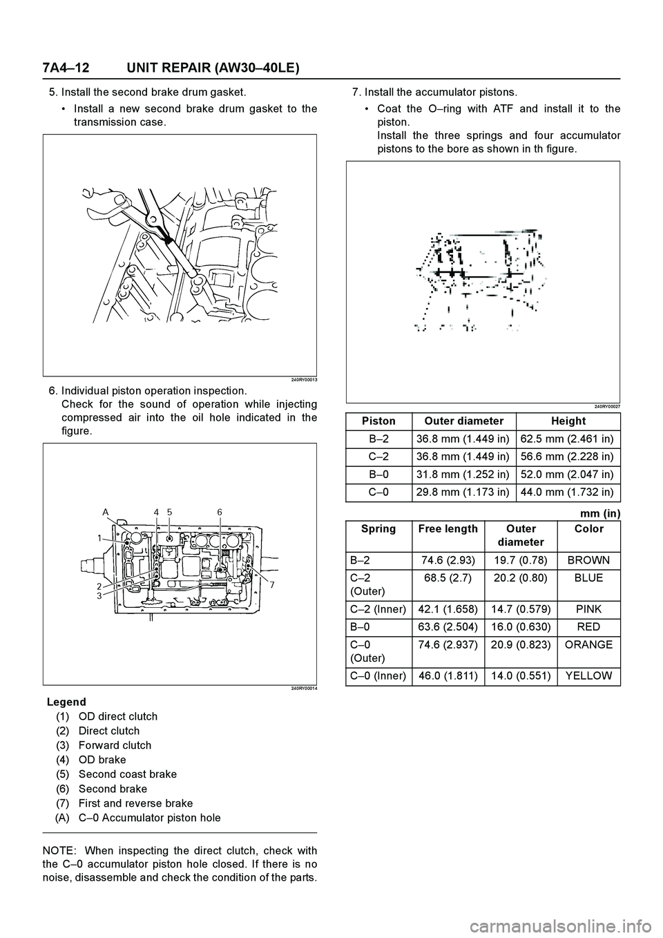
5. Install the second brake drum gasket.
Install a new second brake drum gasket to the
transmission case.
24 0RY 0 001 3
6. Individual piston operation inspection.
Check for the sound of operation while injecting
compressed air into the oil hole indicated in the
figure.
24 0RY 0 001 4
E nd OFCa llou t
NOTE: When inspecting the direct clutch, check with
the C–0 accumulator piston hole closed. If there is no
noise, disassemble and check the condition of the parts.7. Install the accumulator pistons.
Coat the O–ring with ATF and install it to the
piston.
Install the three springs and four accumulator
pistons to the bore as shown in th figure.
24 0RY 0 0027
mm (in)
Legend
(1) OD direct clutch
(2) Direct clutch
(3) Forward clutch
(4) OD brake
(5) Second coast brake
(6) Second brake
(7) First and reverse brake
(A) C–0 Accumulator piston hole
Piston Outer diameter Height
B–2 36.8 mm (1.449 in) 62.5 mm (2.461 in)
C–2 36.8 mm (1.449 in) 56.6 mm (2.228 in)
B–0 31.8 mm (1.252 in) 52.0 mm (2.047 in)
C–0 29.8 mm (1.173 in) 44.0 mm (1.732 in)
Spring Free length Outer
diameterColor
B–2 74.6 (2.93) 19.7 (0.78) BROWN
C–2
(Outer)68.5 (2.7) 20.2 (0.80) BLUE
C–2 (Inner) 42.1 (1.658) 14.7 (0.579) PINK
B–0 63.6 (2.504) 16.0 (0.630) RED
C–0
(Outer)74.6 (2.937) 20.9 (0.823) ORANGE
C–0 (Inner) 46.0 (1.811) 14.0 (0.551) YELLOW
Page 3824 of 4264
7A4–16 UNIT REPAIR (AW30–40LE)
Major Components (3)
Major Components (3) and Associated Parts
24 8L10 0001
E nd O FCallo ut
Legend
(1) Oil pump
(2) Race
(3) OD planetary gear and OD direct clutch
(4) Race
(5) OD planetary ring gear
(6) Snap ring
(7) Flange, plate and disc (B–0)
(8) Bearing and race
(9) Snap ring
(10) OD support
(11) Race
(12) Snap ring
(13) Second coast brake piston assembly
(14) Direct clutch and forward clutch(15) E-ring and pin
(16) Second coast brake band
(17) Front planetary ring gear
(18) Bearing and race
(19) Race
(20) Snap ring
(21) Front planetary gear
(22) Drum and one-way clutch
(23) Snap ring
(24) Flange, plate and disc (B–2)
(25) Snap ring
(26) Rear planetary gear, second brake drum and
output shaft
(27) Bearing
Page 3825 of 4264
UNIT REPAIR (AW30–40LE) 7A4–17
Disassembly
1. Remove seven bolts fix ing the oil pump to the
transmission case.
Remove the oil pump.
24 1RY 0 000 3
2. Remove race from oil pump.
24 1RY 0 000 2
3. Remove the overdrive planetary gear and overdrive
direct clutch with thrust needle bearing from the
transmission case.
25 2L10 0001
4. Remove the race from OD planetary gear.
25 2L10 0017
Page 3829 of 4264
UNIT REPAIR (AW30–40LE) 7A4–21
14. Using snap ring pliers, remove the snap ring.
24 8RY 0 000 6
15. Applying compressed air to the oil hole, remove the
second coast brake piston assembly.
24 8RY 0 000 7
16. Remove the direct clutch and forward clutch from
the transmission case.
24 8RY 0 0008
17. Remove the E-ring from the pin.
Remove the pin from the brake band.
24 8RY 0 0009
Page 3831 of 4264
UNIT REPAIR (AW30–40LE) 7A4–23
NOTE: Hold the output shaft to prevent it from falling.
The output shaft falls when the snap ring is removed.
23. Remove the front planetary gear from the
transmission case.
24 7RY 0 000 7
24. Remove sun gear input drum and one-way clutch.
24 8RY 0 001 2
25. Using two screwdrivers, remove the snap ring.
24 8RY 0 0014
26. Remove, five discs and six plates (B–2).
24 8RY 0 0015
Page 3834 of 4264
7A4–26 UNIT REPAIR (AW30–40LE)
4. Check pack clearance of first and reverse brake.
Using a thickness gauge, measure the clearance
between the plate and second brake drum as shown
in the figure.
Clearance: 0.60 – 1.12 mm (0.0236 – 0.0440 in)
If the values are nonstandard, check for an improper
installation.
24 8RY 0 001 6
5. Install second brake piston sleeve.
24 6RY 0 000 4
6. Install one-way clutch in the transmission case.
24 7RY 0 0011
7. Install discs and plates (B–2).
Instal the 2.5 mm (0.098 in) thick plate with the
rounded edge side of the plate facing the disc.
Alternately install five discs and six plates (Disc first)
24 6RY 0 0005