Page 549 of 4264
CAB 10-41
REMOVAL AND INSTALLATION
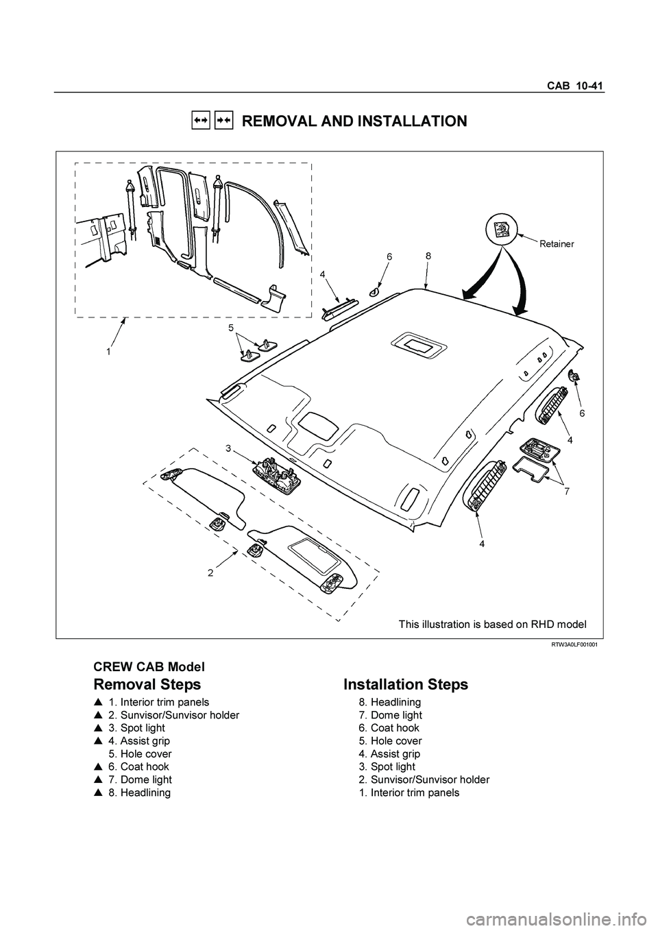
This illustration is based on RHD model
RTW3A0LF001001
CREW CAB Model
Removal Steps
� 1. Interior trim panels
� 2. Sunvisor/Sunvisor holder
� 3. Spot light
� 4. Assist grip
5. Hole cover
� 6. Coat hook
� 7. Dome light
� 8. Headlining
Installation Steps
8. Headlining
7. Dome light
6. Coat hook
5. Hole cover
4. Assist grip
3. Spot light
2. Sunvisor/Sunvisor holder
1. Interior trim panels
Page 550 of 4264
10-42 CAB
Important Operations - Removal
1. Interior Trim Panels
�
Refer to Interior Trim Panels in this section.
2. Sunvisor/Sunvisor Holder
1) Remove the 2 screws fixing the sunvisor.
2) Remove the screw fixing the sunvisor holder.
3. Spot Light
�
Pull out the spot light and disconnect the connector.
4. Assist Grip
�
Remove the 2 fixing screw.
6. Coat Hook
� Open the cover and remove the fixing screw.
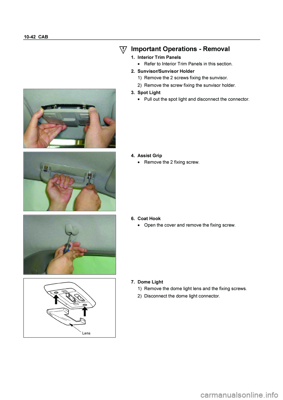
7. Dome Light
1) Remove the dome light lens and the fixing screws.
2) Disconnect the dome light connector.
Page 621 of 4264
CLUTCH 7C-19
SERVICING
Servicing refers to general maintenance procedures to be performed by qualified service personnel.
CLUTCH PEDAL PLAY
Inspection
Depress the clutch pedal lightly by hand, and measure to
determine if the free play is within the standard value.
Pedal Free Play mm(in)
H 5.0-15.0 (0.2-0.6)
Adjustment of the clutch switch (or stopper bolt)
Turn the clutch switch or stopper bolt
1 until the switch bolt
or
stopper bolt
just touches the clutch pedal arm.
Adjust clutch switch
or stopper bolt
by backing it out half a turn,
and measure the clearance (L) between the clutch pedal arm
and the clutch switch bolt end
or stopper bolt.
Lock the lock nut
2.
Connect clutch switch connector.
Clutch switch and clutch pedal
Clearance mm(in)
(L) 0.5-1.5 (0.020-0.059)
Page 660 of 4264
 .................................... 8A- 31
Fuse Location ............................................")
8A-2 ELECTRICAL-BODY AND CHASSIS
PAGE
Fuse and Slow Blow Fuse Location (Relay and Fuse Box) .................................... 8A- 31
Fuse Location ............................................................................................................. 8A- 33
Diode Location ........................................................................................................... 8A- 34
Fuse Block Circuit ...................................................................................................... 8A- 35
Fuse Block Circuit (C24SE) ....................................................................................... 8A- 35
Fuse Block Circuit (6VE1) ......................................................................................... 8A- 37
Fuse Block Circuit (4JA1-TC/4JH1-TC) - RHD ......................................................... 8A- 39
Fuse Block Circuit (4JA1-TC/4JH1-TC) – LHD ......................................................... 8A- 41
Fuse Block Circuit (4JH1-L) ...................................................................................... 8A- 43
Grounding Point ............................................................................................................. 8A- 45
Ground Point .............................................................................................................. 8A- 45
Ground Point Location .............................................................................................. 8A- 61
Main Cable harness Routing .......................................................................................... 8A- 63
C24SE / 6VE1 / 4JA1-L / 4JH1-TC .............................................................................. 8A- 63
Instrument Harness .................................................................................................... 8A- 71
System Repair .................................................................................................................8A- 73
Start and Charging ..................................................................................................... 8A- 73
Engine Control Module (ECM) ................................................................................... 8A- 89
Exhaust Gas Recalculation (EGR): 4JA1-L Only ...................................................... 8A- 109
Lighting ....................................................................................................................... 8A- 114
Front Fog Light ........................................................................................................... 8A- 136
Rear Fog Light ............................................................................................................ 8A- 144
Head Light Leveling ................................................................................................... 8A- 149
Illumination ................................................................................................................. 8A- 154
Hazard Warning Flasher, Turn Signal Light, Back Up Light,
Horn and Stop Light ................................................................................................. 8A- 161
Dome Light, Spot Light and Warning Buzzer .......................................................... 8A- 181
Windshield Wiper and Washer .................................................................................. 8A- 196
Transmission Control Module (TCM) ....................................................................... 8A- 214
Meter, Warning Light and Indicator Light ................................................................ 8A- 223
Heater and Air Conditioning ...................................................................................... 8A- 281
Power Door Lock ....................................................................................................... 8A- 293
Page 661 of 4264

ELECTRICAL-BODY AND CHASSIS 8A-3
PAGE
Power Window ........................................................................................................... 8A- 310
Audio, Clock and Cigarette Lighter .......................................................................... 8A- 329
Power Door Mirror ...................................................................................................... 8A- 337
Rear Defogger ............................................................................................................ 8A- 349
SRS-Air Bag ................................................................................................................ 8A- 358
Transfer Case Control Module .................................................................................. 8A- 361
Anti-Lock Brake System ............................................................................................ 8A- 373
Immobilizer ................................................................................................................. 8A- 376
Keyless Entry ............................................................................................................. 8A- 385
Anti Theft ....................................................................................................................8A- 400
Auto Cruise ................................................................................................................. 8A- 412
Trailer Hitch ................................................................................................................ 8A- 415
Connector List ................................................................................................................8A- 418
Page 662 of 4264

8A-4 ELECTRICAL-BODY AND CHASSIS
GENERAL INFORMATION
The body and chassis electrical system operates on a twelve volt power supply with negative ground polarity.
The main harness consists of the engine harness, the instrument harness, the body harness, and the chassis
harness.
The harnesses use a split corrugated tube to protect the wires from the elements.
Wire size is determined by current flow, circuit length, and voltage drop.
All wires have color-coded insulation.
Wire color-codes are shown in the circuit diagrams.
This makes it easier to trace circuits and to make the proper connections.
Each circuit consists of the following:
1. Power source - The battery and the alternator
2. Wires - To carry electrical current through the circuit
3. Fuses - To protect the circuit against current overload
4. Relays - To protect voltage drop between the battery and the circuit parts and to protect the switch points against
burning
5. Switches - To open and close the circuit
6. Load - Any device, such as a light or motor, which converts the electrical current into useful work
7. Ground - To allow the current to flow back to the power source
Page 663 of 4264

ELECTRICAL-BODY AND CHASSIS 8A-5
NOTES FOR WORKING ON ELECTRICAL ITEMS
Battery
BATTERY CABLE
Disconnecting the Battery Cable
1. All switches should be "OFF" position.
2. Disconnect the battery ground cable.
3. Disconnect the battery positive cable.
CAUTION:
It is important that the battery ground cable be
disconnected first.
Disconnecting the battery positive cable first can result in
a short circuit.
Connecting the Battery Cable
Follow the disconnecting procedure in the reverse order to
connect the battery cables.
CAUTION:
Clean the battery terminal and apply light coat of grease to
prevent terminal corrosion.
CONNECTOR HANDLING
Disconnecting the Connectors
Some connectors have a tang lock to hold the connectors
together during vehicle operation.
Some tang locks are released by pulling them towards you
1.
Other tang locks are released by pressing them forward
2.
Determine which type of tang lock is on the connector being
handled.
Firmly grasp both sides (male and female) of the connector.
Release the tang lock and carefully pull the two halves of the
connector apart.
Never pull on the wires to separate the connectors.
This will result in wire breakage.
Page 669 of 4264
ELECTRICAL-BODY AND CHASSIS 8A-11
SYMBOLS AND ABBREVIATIONS
SYMBOLS
Symbol Meaning of Symbol Symbol Meaning of Symbol
Fuse
Bulb
Fusible link
Double filament bulb
Fusible link wire
Motor
Switch
Variable resistor Rheostat
Switch
Coil (inductor), solenoid,
magnetic valve
Switch (Normal close type)
Contact wiring
Relay
Battery
Diode
Connector
Electronic Parts
Light emitting diode
Resistor
Reed switch
Speaker
Condenser
Buzzer
Horn
Circuit breaker
Vacuum switching valve