2004 ISUZU TF SERIES jump start
[x] Cancel search: jump startPage 2135 of 4264
3.5L ENGINE DRIVEABILITY AND EMISSIONS 6E-139
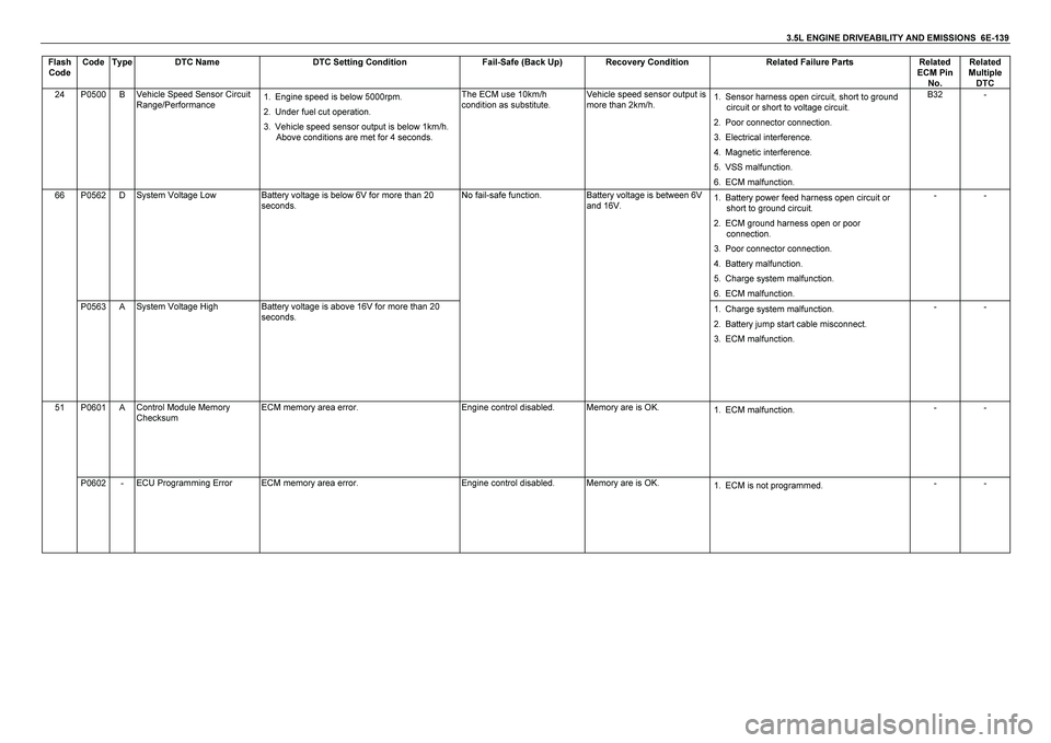
Flash
Code Code Type DTC Name DTC Setting Condition Fail-Safe (Back Up) Recovery Condition Related Failure Parts Related
ECM Pin
No. Related
Multiple
DTC 24 P0500 B Vehicle Speed Sensor Circuit
Range/Performance 1. Engine speed is below 5000rpm.
2. Under fuel cut operation.
3. Vehicle speed sensor output is below 1km/h.
Above conditions are met for 4 seconds. The ECM use 10km/h
condition as substitute. Vehicle speed sensor output is
more than 2km/h. 1. Sensor harness open circuit, short to ground
circuit or short to voltage circuit.
2. Poor connector connection.
3. Electrical interference.
4. Magnetic interference.
5. VSS malfunction.
6. ECM malfunction. B32 -
P0562 D System Voltage Low Battery voltage is below 6V for more than 20
seconds. 1. Battery power feed harness open circuit or
short to ground circuit.
2. ECM ground harness open or poor
connection.
3. Poor connector connection.
4. Battery malfunction.
5. Charge system malfunction.
6. ECM malfunction. - -
66
P0563 A System Voltage High Battery voltage is above 16V for more than 20
seconds. No fail-safe function. Battery voltage is between 6V
and 16V.
1. Charge system malfunction.
2. Battery jump start cable misconnect.
3. ECM malfunction. - - 51 P0601 A Control Module Memory
Checksum ECM memory area error. Engine control disabled. Memory are is OK.
1. ECM malfunction. - -
P0602 - ECU Programming Error ECM memory area error. Engine control disabled. Memory are is OK.
1. ECM is not programmed. - -
Page 2408 of 4264
6-2 ENGINE DIAGNOSIS (C24SE)
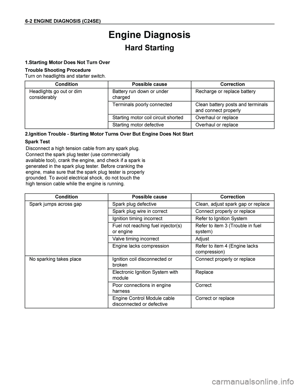
Engine Diagnosis
Hard Starting
1.Starting Motor Does Not Turn Over
Trouble Shooting Procedure
Turn on headlights and starter switch.
Condition Possible cause Correction
Headlights go out or dim
considerably Battery run down or under
charged Recharge or replace battery
Terminals poorly connected Clean battery posts and terminals
and connect properly
Starting motor coil circuit shorted Overhaul or replace
Starting motor defective Overhaul or replace
2.Ignition Trouble - Starting Motor Turns Over But Engine Does Not Start
Spark Test
Disconnect a high tension cable from any spark plug.
Connect the spark plug tester (use commercially
available tool), crank the engine, and check if a spark is
generated in the spark plug tester. Before cranking the
engine, make sure that the spark plug tester is properly
grounded. To avoid electrical shock, do not touch the
high tension cable while the engine is running.
Condition Possible cause Correction
Spark jumps across gap Spark plug defective Clean, adjust spark gap or replace
Spark plug wire in correct Connect properly or replace
Ignition timing incorrect Refer to Ignition System
Fuel not reaching fuel injector(s)
or engine Refer to item 3 (Trouble in fuel
system)
Valve timing incorrect Adjust
Engine lacks compression Refer to item 4 (Engine lacks
compression)
No sparking takes place Ignition coil disconnected or
broken Connect properly or replace
Electronic Ignition System with
module Replace
Poor connections in engine
harness Correct
Engine Control Module cable
disconnected or defective Correct or replace
Page 2531 of 4264
ENGINE FUEL (C24SE) 6C-7
Fuel Pump Flow Test
If reduction of fuel supply is suspected, perform the
following checks.
1. Make sure that there is fuel in the tank.
2. With the engine running, check the fuel feed pipe
and hose from fuel tank to injector for evidence o
f
leakage. Retighten, if pipe or hose connection is
loose. Also, check pipes and hoses for squashing
or clogging.
3. Insert the hose from fuel feed pipe into a clean
container, and check for fuel pump flow rate.
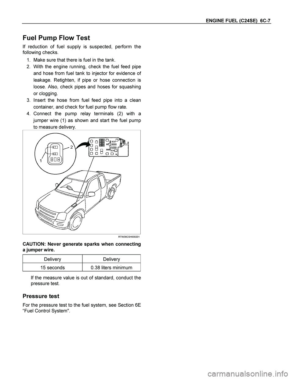
4. Connect the pump relay terminals (2) with a
jumper wire (1) as shown and start the fuel pump
to measure delivery.
RTW36CSH000201
CAUTION: Never generate sparks when connecting
a jumper wire.
Delivery Delivery
15 seconds 0.38 liters minimum
If the measure value is out of standard, conduct the
pressure test.
Pressure test
For the pressure test to the fuel system, see Section 6E
“Fuel Control System".
Page 2543 of 4264
ENGINE ELECTRICAL 6D1-1
SECTION 6D1
ENGINE ELECTRICAL
CONTENTS
PAGE
Battery ............................................................................................................................. 6D1- 2
General Description ................................................................................................... 6D1- 2
Service Precaution ..................................................................................................... 6D1- 2
Diagnosis .................................................................................................................... 6D1- 3
Battery Charging ........................................................................................................ 6D1- 4
Jump Starting ............................................................................................................. 6D1- 4
Removal ...................................................................................................................... 6D1- 6
Installation .................................................................................................................. 6D1- 6
Main Data and Specifications ................................................................................... 6D1- 6
Page 2546 of 4264

6D1-4 ENGINE ELECTRICAL
Battery Charging
Observe the following safety precautions when charging the
battery:
1. Never attempt to charge the battery when the fluid level is
below the lower level line on the side of the battery. In this
case, the battery must be replaced.
2. Pay close attention to the battery during charging
procedure.
Battery charging should be discontinued or the rate o
f
charge reduced if the battery feels hot to the touch.
Battery charging should be discontinued or the rate o
f
charge reduced if the battery begins to gas or spew
electrolyte from the vent holes.
3. In order to more easily view the hydrometer blue dot or ring,
it may be necessary to jiggle or tilt the battery.
4. Battery temperature can have a great effect on battery
charging capacity.
5. The sealed battery used on this vehicle may be either quick
charged or slow charged in the same manner as othe
r
batteries.
Whichever method you decide to use, be sure that you
completely charge the battery. Never partially charge the
battery.
Jump Starting
Jump Starting with an Auxiliary (Booster)
Battery
CAUTION: Never push or tow the vehicle in an attempt to
start it. Serious damage to the emission system as well as
other vehicle parts will result.
Treat both the discharged battery and the booster battery
with great care when using jumper cables.
Carefully follow the jump starting procedure, being careful
at all times to avoid sparking.
WARNING: FAILURE TO CAREFULLY FOLLOW THE JUMP
STARTING PROCEDURE COULD RESULT IN THE
FOLLOWING:
1. Serous personal injury, particularly to your eyes.
2. Property damage from a battery explosion, battery acid, o
r
an electrical fire.
3. Damage to the electronic components of one or both
vehicles particularly.
Never expose the battery to an open flame or electrical spark.
Gas generated by the battery may catch fire or explode.
Remove any rings, watches, or other jewelry before working
around the battery. Protect your eyes by wearing an approved
set of goggles.
Never allow battery fluid to come in contact with your eyes or
skin.
Never allow battery fluid to come in contact with fabrics or
painted surfaces.
Page 2547 of 4264
ENGINE ELECTRICAL 6D1-5
Battery fluid is a highly corrosive acid.
Should battery fluid come in contact with your eyes, skin,
fabric, or a painted surface, immediately and thoroughly rinse
the affected area with clean tap water.
Never allow metal tools or jumper cables to come in contact
with the positive battery terminal, or any other metal surface of
the vahicle. This will protect against a short circuit.
Always keep batteries out of reach of young children.
Jump Starting Procedure
1. Set the vehicle parking brake.
If the vahicle is equipped with an automatic transmission,
place the selector level in the "PARK" position.
If the vehicle is equipped with a manual transmission, place
the shift lever in the "NEUTRAL" position.
Turn "OFF" the ignition.
Turn "OFF" all lights and any other accessory requiring
electrical power.
2. Look at the built-in hydrometer.
If the indication area of the built-in hydrometer is completely
clear, do not try to jump start.
3.
Attach the end of one jumper cable to the positive terminal
of the booster battery.
Attach the other end of the same cable to the positive
terminal of the discharged battery.
Do not allow the vehicles to touch each other. This will
cause a ground connection, effectively neutralizing the
charging procedure.
Be sure that the booster battery has a 12 volt rating.
4.
Attach one end of the remaining cable to the negative
terminal of the booster battery.
Attach the other end of the same cable to a solid engine
ground (such as the air conditioning compressor bracket o
r
the generator mounting bracket) of the vehicle with the
discharged battery.
The ground connection must be at least 450 mm (18 in.)
from the battery of the vehicle whose battery is being
charged.
WARNING: NEVER ATTACH THE END OF THE JUMPER
CABLE DIRECTLY TO THE NEGATIVE TERMINAL OF THE
DEAD BATTERY.
5. Start the engine of the vehicle with the good battery.
Make sure that all unnecessary electrical accessories have
been turned "OFF".
6. Start the engine of the vehicle with the dead battery.
7. To remove the jumper cables, follow the above directions in
reverse order.
Be sure to first disconnect the negative cable from the
vehicle with the discharged battery.
Page 2630 of 4264
6E–54 ENGINE DRIVEABILITY AND EMISSIONS
GENERAL DESCRIPTION FOR ELECTRIC
IGNITION SYSTEM
The engine use two ignition coils, one per two cylinders.
A two wire connector provides a battery voltage primary
supply through the ignition fuse.
The ignition control spark timing is the ECM’s method of
controlling the spark advance and the ignition dwell.
The ignition control spark advance and the ignition dwell
are calculated by the ECM using the following inputs.
Engine speed
Crankshaft position (CKP) sensor
Engine coolant temperature (ECT) sensor
Throttle position sensor
Vehicle speed sensor
ECM and ignition system supply voltage
Ignition coil works to generate only the secondary
voltage be receiving the primary voltage from ECM.
The primary voltage is generated at the coil driver
located in the ECM. The coil driver generate the primary
voltage based on the crankshaft position signal. In
accordance with the crankshaft position signal, ignition
coil driver determines the adequate ignition timing and
also cylinder number to ignite.
Ignition timing is determined the coolant temperature,
intake air temperature, engine speed, engine load,
knock sensor signal, etc.
Spark Plug
Although worn or dirty spark plugs may give satisfactory
operation at idling speed, they frequently fail at higher
engine speeds. Faulty spark plugs may cause poor fuel
economy, power loss, loss of speed, hard starting and
generally poor engine performance. Follow the
scheduled maintenance service recommendations to
ensure satisfactory spark plug performance. Refer to
Maintenance and Lubrication.
Normal spark plug operation will result in brown to
grayish-tan deposits appearing on the insulator portion
of the spark plug. A small amount of red-brown, yellow,
and white powdery material may also be present on the
insulator tip around the center electrode. These
deposits are normal combustion by-products of fuels
and lubricating oils with additives. Some electrode wear
will also occur. Engines which are not running properly
are often referred to as “misfiring.” This means the
ignition spark is not igniting the air/fuel mix ture at the
proper time. While other ignition and fuel system causes
must also be considered, possible causes include
ignition system conditions which allow the spark voltage
to reach ground in some other manner than by jumping
across the air gap at the tip of the spark plug, leaving
the air/fuel mix ture unburned. Misfiring may also occur
when the tip of the spark plug becomes overheated and
ignites the mixture before the spark jumps. This is
referred to as “pre-ignition.”
Spark plugs may also misfire due to fouling, ex cessive
gap, or a cracked or broken insulator. If misfiring occursbefore the recommended replacement interval, locate
and correct the cause.
Carbon fouling of the spark plug is indicated by dry,
black carbon (soot) deposits on the portion of the spark
plug in the cylinder. Ex cessive idling and slow speeds
under light engine loads can keep the spark plug
temperatures so low that these deposits are not burned
off. Very rich fuel mix tures or poor ignition system output
may also be the cause. Refer to DTC P1167.
Oil fouling of the spark plug is indicated by wet oily
deposits on the portion of the spark plug in the cylinder,
usually with little electrode wear. This may be caused by
oil during break-in of new or newly overhauled engines.
Deposit fouling of the spark plug occurs when the
normal red-brown, yellow or white deposits of
combustion by-products become sufficient to cause
misfiring. In some cases, these deposits may melt and
form a shiny glaze on the insulator around the center
electrode. If the fouling is found in only one or two
cylinders, valve stem clearances or intake valve seals
may be allowing ex cess lubricating oil to enter the
cylinder, particularly if the deposits are heavier on the
side of the spark plug facing the intake valve.
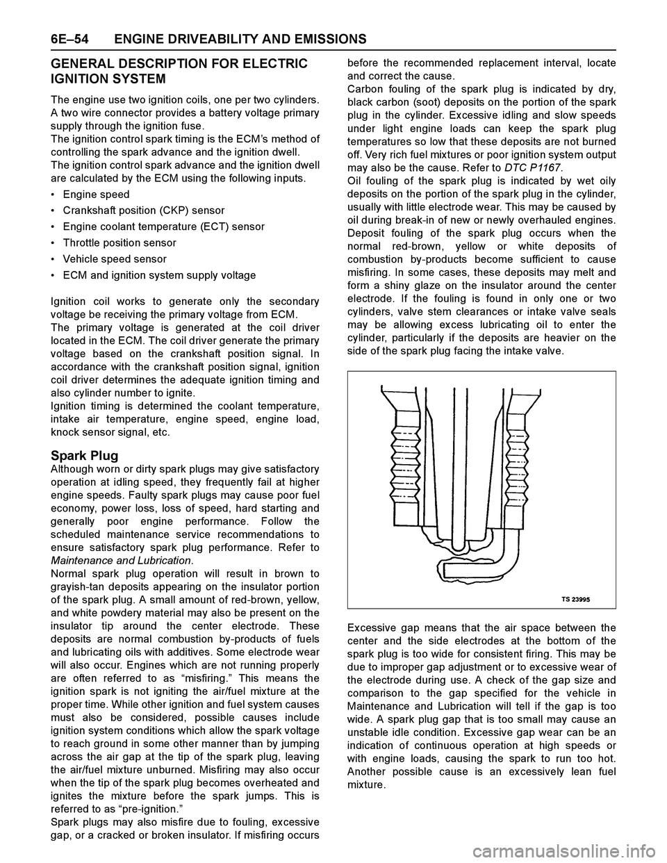
Ex cessive gap means that the air space between the
center and the side electrodes at the bottom of the
spark plug is too wide for consistent firing. This may be
due to improper gap adjustment or to ex cessive wear of
the electrode during use. A check of the gap size and
comparison to the gap specified for the vehicle in
Maintenance and Lubrication will tell if the gap is too
wide. A spark plug gap that is too small may cause an
unstable idle condition. Ex cessive gap wear can be an
indication of continuous operation at high speeds or
with engine loads, causing the spark to run too hot.
Another possible cause is an ex cessively lean fuel
mixture.
Page 2685 of 4264
ENGINE DRIVEABILITY AND EMISSIONS 6E–109
The fuel injector(s).
4. Fuel pressure that drops off during acceleration,
cruise, or hard cornering may case a lean condition.
A lean condition can cause a loss of power, surging,
or misfire. A lean condition can be diagnosed using a
Tech 2 Scan Tool.
Following are applicable to the vehicle with
closed Loop System:
If an ex tremely lean condition occurs, the ox ygen
sensor(s) will stop toggling. The ox ygen sensor
output voltage(s) will drop below 500 mV. Also, the
fuel injector pulse width will increase.
Important: Make sure the fuel system is not
operating in the “Fuel Cut-Off Mode.”
When the engine is at idle, the manifold pressure is
low (high vacuum). This low pressure (high vacuum)
is applied to the fuel pressure regulator diaphragm.
The low pressure (high vacuum) will offset the
pressure being applied to the fuel pressure regulator
diaphragm by the spring inside the fuel pressure
regulator. When this happens, the result is lower fuel
pressure. The fuel pressure at idle will vary slightly
as the barometric pressure changes, but the fuel
pressure at idle should always be less than the fuel
pressure noted in step 2 with the engine OFF.
16.Check the spark plug associated with a particular
fuel injector for fouling or saturation in order to
determine if that particular fuel injector is leaking. If
checking the spark plug associated with a particular
fuel injector for fouling or saturation does not
determine that a particular fuel injector is leaking,
use the following procedure:
Remove the fuel rail, but leave the fuel lines and
injectors connected to the fuel rail. Refer to Fuel
Rail Assembly in On-Vehicle Service.
Lift the fuel rail just enough to leave the fuel
injector nozzles in the fuel injector ports.
Caution: In order to reduce the risk of fire and
personal injury that may result from fuel
spraying on the engine, verify that the fuel rail is
positioned over the fuel injector ports and verify
that the fuel injector retaining clips are intact.
Pressurize the fuel system by connecting a 20
amp fused jumper between B+ and the fuel
pump relay connector.
Visually and physically inspect the fuel
injector nozzles for leaks.
17.A rich condition may result from the fuel pressure
being above 376 kPa (55 psi). A rich condition may
cause a 45 to set. Driveability conditions associatedwith rich conditions can include hard starting
(followed by black smoke) and a strong sulfur smell
in the ex haust.
20.This test determines if the high fuel pressure is due
to a restricted fuel return line or if the high fuel
pressure is due to a faulty fuel pressure regulator.
21.A lean condition may result from fuel pressure below
333 kPa (48 psi). A lean condition may cause a 44 to
set. Driveability conditions associated with lean
conditions can include hard starting (when the
engine is cold), hesitation, poor driveability, lack of
power, surging, and misfiring.
22.Restricting the fuel return line causes the fuel
pressure to rise above the regulated fuel pressure.
Command the fuel pump ON with the scan tool. The
fuel pressure should rise above 376 kPa (55 psi) as
the fuel return line becomes partially closed.
NOTE: Do not allow the fuel pressure to exceed 414
kPa (60 psi). Fuel pressure in excess of 414 kPa (60
psi) may damage the fuel pressure regulator.
Caution: To reduce the risk of fire and personal
injury:
It is necessary to relieve fuel system pressure
before connecting a fuel pressure gauge.
Refer to Fuel Pressure Relief Procedure,
below.
A small amount of fuel may be released when
disconnecting the fuel lines. Cover fuel line
fittings with a shop towel before
disconnecting, to catch any fuel that may leak
out. Place the towel in an approved container
when the disconnect is completed.
Fuel Pressure Relief Procedure
1. Remove the fuel cap.
2. Located on the intake manifold which is at the top
right part of the engine.
3. Start the engine and allow it to stall.
4. Crank the engine for an additional 3 seconds.
Fuel Pressure Gauge Installation
1. Remove the fuel pressure fitting cap.
2. Install fuel pressure gauge 5-8840-0378-0 to the
fuel feed line located on the upper right side of the
engine.
3. Reinstall the fuel pump relay.