Page 1112 of 4264
 YES NO
1
1. Turn the starter switch off.
2. Disconnect the actuator connector C–119.
3. Mea")
8B-14 CRUISE CONTROL SYSTEM
DTC 1–2 Clutch System Open or Short Circuit
Step Action Value(s) YES NO
1
1. Turn the starter switch off.
2. Disconnect the actuator connector C–119.
3. Measure resistance between actuator side
connector terminal 3 and 4.
Is there resistance within range specified in the
value(s) column?
34.7 –
42.4�
Go to Step 2
Replace the
actuator
2
1. Disconnect the brake switch connector C–44.
2. Check continuity between switch side connector
terminal 3 and 4.
Is there continuity between terminals?
—
Go to Step 3
Replace the
switch
3
1. Reconnect the brake switch connector C–44.
2. Check continuity between harness side connector
C–120 terminal 6 and connector C–44 terminal 3,
connector C–119 terminal 4 and connector C–120
terminal 8.
Is there continuity between terminals?
—
Go to Step 4
Replace open
circuit
4 Check continuity between harness side connector
C–119 terminal 3 and the ground, connector C–119
terminal 4 and the ground, connector C–120
terminal 6 and the ground.
Are the results same as specified in the value(s)
column?
No
continuity
Replace the
control unit
Repair short
circuit
Page 1113 of 4264
 YES NO
1
1. Turn the starter switch off.
2. Disconnect the actuator connector C–119.
3. Connect the battery p")
CRUISE CONTROL SYSTEM 8B-15
DTC 1–3 Mechanical Defect
Step Action Value(s) YES NO
1
1. Turn the starter switch off.
2. Disconnect the actuator connector C–119.
3. Connect the battery positive terminal with the
actuator side connector terminal 3 and the battery
negative terminal with terminal 4.
Does the control plate move by hand?
—
Replace the
actuator
Go to Step 2
2 Connect the battery positive terminal with the
actuator side connector terminal 1 and 3, and the
battery negative terminal with terminal 2 and 4.
Does the control plate move to full open side?
—
Go to Step 3
Replace the
actuator
3 Connect the battery positive terminal with the
actuator side connector terminal 2 and 3, and the
battery negative terminal with terminal 1 and 4.
Does the control plate move to full close side?
—
Go to Step 4
Replace the
actuator
4 Is there continuity between harness side connector
C–119 terminal 1 and connector C–120 terminal 7,
connector C–119 terminal 2 and connector C–120
terminal 15?
—
Replace the
control unit
Repair or
replace
harness
Page 1114 of 4264
8B-16 CRUISE CONTROL SYSTEM
DTC 1–4 Close Side of Motor System Open Circuit
Step Action Value(s) YES NO
1
1. Turn the starter switch off.
2. Disconnect the actuator connector C–119.
3. Measure resistance between actuator side
connector terminal 1 and 2.
If control plate position is fully opened or fully
closed, resistance can not be measured.
Is there resistance within range specified in the
value(s) column?
More than
4.2�
Go to Step 2
Replace the
actuator
2 Is there continuity between harness side connector
C–119 terminal 1 and connector C–120 terminal 7,
harness side connector C–119 terminal 2 and
connector C–120 terminal 15?
—
Replace the
control unit
Repair or
replace the
harness
Page 1115 of 4264
CRUISE CONTROL SYSTEM 8B-17
DTC 2–1 Signal of Vehicle Speed Malfunction
Step Action Value(s) YES NO
1 Check the DTC for engine.
Is the vehicle speed sensor DTC set?
—
Go to DTC for
engine
Go to Step 2
2 Check continuity between harness side connector
E–44 terminal 3 and connector C–120 terminal 9.
Is there continuity between terminals?
—
Go to Step 3
Replace open
circuit
3 Check the continuity between harness side
connector E–44 terminal 3 and ground, connector
C–120 terminal 9 and ground.
Are the results same as specified in the value(s)
column?
No continuity
Replace the
control unit
Repair short
circuit
Page 1116 of 4264
 YES NO
1
1. Turn the starter switch off.
2. Disconnect the auto cruise control unit")
8B-18 CRUISE CONTROL SYSTEM
DTC 3–1 Turning On Switch at All time or at the same time
Step Action Value(s) YES NO
1
1. Turn the starter switch off.
2. Disconnect the auto cruise control unit connector
C-120.
3. Turn the starter switch on.
4. Turn the cruise control switch “cancel”.
5. Check voltage at the harness side connector C–
120 terminal 10, terminal 3 and terminal 4.
Is the voltage specified value?
0V
Go to Step 3
Go to Step 2
2
1. Turn the starter switch off.
2. Disconnect the cruise control switch connector B–
59.
3. Check voltage at the harness side connector C–
120 terminal 10, terminal 3 and terminal 4.
Is the voltage specified value?
0V
Replace the
cruise control
switch
Repair short
circuit
3
1. Turn the starter switch off.
2. Turn the cruise control switch “cancel”.
3. Check the continuity between harness side
connector C–120 terminal 10 and terminal 3,
connector C–120 terminal 3 and terminal 4,
connector C–120 terminal 10 and terminal 4.
Are the results same as specified in the value(s)
column?
No continuity
Go to Step 5
Go to Step 4
4
1. Disconnect the cruise control switch connector B–
59.
2. Check the continuity between harness side
connector C–120 terminal 10 and terminal 3,
connector C–120 terminal 3 and terminal 4,
connector C–120 terminal 10 and terminal 4.
Are the results same as specified in the value(s)
column?
No continuity
Replace the
cruise control
switch
Repair short
circuit
5 Check the continuity between harness side
connector C–120 terminal 10 and connector B–59
terminal 10.
Is there continuity between terminals?
—
Replace the
control unit
Replace open
circuit
Page 1873 of 4264
 6A-49
Engine Assembly
Removal
P1010068
1. Disconnect battery ground and positive cable.
2. Remove battery.
3. Make alignment mark on the engine hood and
h")
ENGINE MECHANICAL (6VE1 3.5L) 6A-49
Engine Assembly
Removal
P1010068
1. Disconnect battery ground and positive cable.
2. Remove battery.
3. Make alignment mark on the engine hood and
hinges before removal in order to return the hood
to original position exactly.
4. Remove engine hood.
5. Drain radiator coolant.
6. Disconnect accelerator cable and automatic cruise
control cable from throttle valve on common
chamber.
7. Remove the ECM.
� Disconnect the two connectors from the ECM.
� . Remove fixing bolts on the common chamber.
� Remove fixing bolts for ground cable.
8. Disconnect air duct with air cleaner cover.
9. Remove air cleaner assembly.
10. Disconnect canister vacuum hose.
11. Disconnect vacuum booster hose.
12. Disconnect three engine harness connectors.
13. Disconnect harness connector to transmission (lef
t
front side of engine compartment), disconnect shift
on the fly harness connector from front side o
f
front axle and remove transmission harness
bracket from engine left side.
14. Disconnect ground cable between engine and
frame.
15. Disconnect bonding cable connector on the back
of right dash panel.
16. Disconnect bonding cable terminal on the lef
t
bank.
17. Disconnect starter harness connector from starter.
18. Disconnect generator harness connector from
generator.
19. Disconnect coolant reserve tank hose from
radiator.
20. Remove radiator upper and lower hoses.
21. Remove upper fan shroud.
22. Remove cooling fan assembly four fixing nuts,
then the cooling fan assembly.
23. Move drive belt tensioner to loose side using
wrench then remove drive belt.
24. Remove power steering pump fixing bolts, then
power steering pump. Place the power steering
pump along with piping on the body side.
25. Remove air conditioning compressor fixing bolts
from bracket and place the compressor along with
piping on the body side.
26. Remove four O2 sensor harness connectors (two
each bank) from exhaust front pipe.
27. Remove three exhaust pipe fixing nuts from each
bank.
28. Remove two exhaust pipe fixing nuts from each
exhaust pipe, then move exhaust pipe to rear side
of vehicle.
29. Remove flywheel dust covers.
30. Disconnect two heater hoses from engine.
31. Disconnect fuel hose from right side o
f
transmission.
CAUTION: Plug fuel pipe on engine side and fuel
hose from fuel tank.
32. Remove transmission assembly. Refer to
Transmission section in this manual.
33. Support the engine by engine hoist.
34. Remove two left side engine mount fixing bolts
from engine mount on chassis side.
35. Remove two right side engine mount fixing bolts
from engine mount on chassis side.
36. Remove engine assembly.
Installation
CAUTION: When assembling the engine and
transmission, confirm that dowels have been
mounted in the specified positions at the engine
side. Also take care that dowel positions are
different between the manual transmission and the
automatic transmission. Otherweise, the
transmission may be damaged.
Page 2002 of 4264
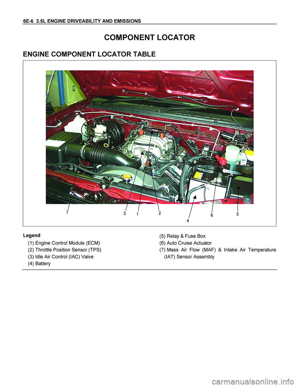
6E-6 3.5L ENGINE DRIVEABILITY AND EMISSIONS
COMPONENT LOCATOR
ENGINE COMPONENT LOCATOR TABLE
�
��� ��
�
Legend
(1) Engine Control Module (ECM)
(2) Throttle Position Sensor (TPS)
(3) Idle Air Control (IAC) Valve
(4) Battery
(5) Relay & Fuse Box
(6) Auto Cruise Actuator
(7) Mass Air Flow (MAF) & Intake Air Temperature
(IAT) Sensor Assembly
Page 2058 of 4264
 SYSTEM
Linear EGR Valve
060R200237
Legend
(1) ECM
(2) Linear EGR Valve")
6E-62 3.5L ENGINE DRIVEABILITY AND EMISSIONS
GENERAL DESCRIPTION FOR EXHAUST
GAS RECIRCULATION (EGR) SYSTEM
Linear EGR Valve
060R200237
Legend
(1) ECM
(2) Linear EGR Valve
(3) Throttle
(4) Exhaust Manifold
The exhaust gas re-circulation (EGR) system is used to
reduce emission levels of oxides of nitrogen (NOx).
NOx emission levels are caused by a high combustion
levels by decreasing the combustion temperature.
The EGR valve feeds small amount of exhaust gas
back into the combustion chamber. The fuel/air mixture
will be diluted and combustion temperatures reduced.
Linear EGR valve Operation and Results o
f
Incorrect Operation
The linear EGR valve is designed to accurately supply
EGR to the engine independent of intake manifold
vacuum. The valve controls EGR flow from the exhaus
t
to the intake manifold through an orifice with a ECM
controlled pintle. During operation, the ECM controls
pintle position by monitoring the pintle position feedback
signal.
The linear EGR valve is activated under the following
conditions:
� No DTC relating to the EGR.
� Engine speed is between 1200 and 4375rpm.
� Engine coolant temperature is between 20 and
100�.
� Throttle position sensor output voltage is belo
w
3V.
Too mach EGR flow at idle, cruise or cold operation
may cause any of the following conditions to occur:
� Engine stalls after a cold start.
� Engine stalls at idle after deceleration.
� Vehicle surges during cruise.
� Rough idle.
Too little or no EGR flow may allow combustion
temperatures to get too high. This could cause:
� Spark knock (detonation).
� Emission test failure.
� Poor fuel economy.
 YES NO
1
1. Turn the starter switch off.
2. Disconnect the actuator connector C–119.
3.")
 YES NO
1 Check the DTC for engine.
Is the vehicle speed sensor DTC set?
—
Go to DTC for
engi")