Page 664 of 4264

8A-6 ELECTRICAL-BODY AND CHASSIS
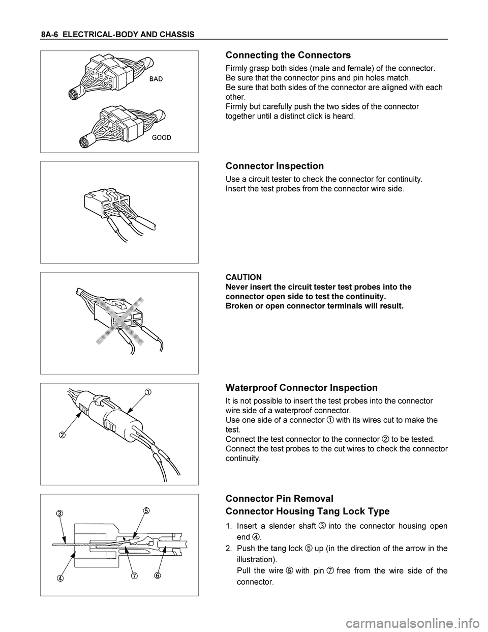
Connecting the Connectors
Firmly grasp both sides (male and female) of the connector.
Be sure that the connector pins and pin holes match.
Be sure that both sides of the connector are aligned with each
other.
Firmly but carefully push the two sides of the connector
together until a distinct click is heard.
Connector Inspection
Use a circuit tester to check the connector for continuity.
Insert the test probes from the connector wire side.
CAUTION
Never insert the circuit tester test probes into the
connector open side to test the continuity.
Broken or open connector terminals will result.
Waterproof Connector Inspection
It is not possible to insert the test probes into the connector
wire side of a waterproof connector.
Use one side of a connector
1 with its wires cut to make the
test.
Connect the test connector to the connector
2 to be tested.
Connect the test probes to the cut wires to check the connecto
r
continuity.
Connector Pin Removal
Connector Housing Tang Lock Type
1. Insert a slender shaft 3into the connector housing open
end
4.
2. Push the tang lock
5up (in the direction of the arrow in the
illustration).
Pull the wire
6 with pin 7free from the wire side of the
connector.
Page 1091 of 4264
ELECTRICAL-BODY AND CHASSIS 8A-433
No. Connector face No. Connector face
H-1
White
Battery (+) ~ Engine room H-10
WhiteINST ~ Front Door-RH
H-2
NOT USED H-11
NOT USED
H-3
(6VE1,
4JH1-TC)
White Battery (+) ~ Engine room H-12
BlackINST ~ Roof
H-4
(C24SE)
White Engine room ~ Mission H-13
WhiteINST ~ Door -LH
H-4
(6VE1,
4JA1-TC,
4JH1-TC)
White
Engine ~ Engine room H-14
WhiteRear body ~ Rear door-LH
H-5
NOT USED H-15
White
Engine room ~ Chassis
H-6
White
Engine room ~ INST H-16
WhiteRear body ~ Rear door-RH
H-7
White
Engine room ~ INST H-17
WhiteChassis ~ License plate lamp
H-8
NOT USED H-18
White
Engine room ~ INST
H-9
Blue
Engine room ~ Chassis H-19
~
H-21 NOT USED
Page 1474 of 4264
6E–102 4JA1/4JH1 ENGINE DRIVEABILITY AND EMISSIONS
HOW TO USE BREAKER BOX
The engine control module (ECM) and other connectors
have water proof connector and special terminal. Water
proof terminal does not allow to use back prove. In
addition, the engine control module (ECM) special
terminal can not let regular digital voltage meter prove
to access, because terminal shape is very fin pin type.
In order to prevent damage of female terminal and
connector itself, the breaker box and adapter is the
most suitable special tool.
���
(1) Engine Control Module (ECM)
(2) Harness Adapter(3) Breaker Box
Page 1827 of 4264

ENGINE MECHANICAL (6VE1 3.5L) 6A-3
General Description
Engine Cleanliness And Care
An automobile engine is a combination of many
machined, honed, polished and lapped surfaces with
tolerances that are measured in the thousandths of a
millimeter (ten thousandths of an inch). Accordingly,
when any internal engine parts are serviced, care and
cleanliness are important. Throughout this section, i
t
should be understood that proper cleaning and
protection of machined surfaces and friction areas is
part of the repair procedure. This is considered
standard shop practice even if not specifically stated.
�
A liberal coating of engine oil should be applied to
all friction areas during assembly to protect and
lubricate the surfaces on initial operation.
� Whenever valve train components, pistons, piston
rings, connecting rods, rod bearings, and
crankshaft journal bearings are removed fo
r
service, they should be retained in order.
�
At the time of installation, they should be installed
in the same locations and with the same mating
surfaces as when removed.
� Battery cables should be disconnected before any
major work is performed on the engine. Failure to
disconnect cables may result in damage to wire
harness or other electrical parts.
� The six cylinders of this engine are identified by
numbers; Right side cylinders 1, 3 and 5, Left side
cylinders 2, 4 and 6, as counted from crankshaf
t
pulley side to flywheel side.
General Information on Engine Service
The following information on engine service should be
noted carefully, as it is important in preventing damage
and contributing to reliable engine performance.
� When raising or supporting the engine for any
reason, do not use a jack under the oil pan. Due to
the small clearance between the oil pan and the oil
pump strainer, jacking against the oil pan may
cause damage to the oil pick-up unit.
� The 12-volt electrical system is capable o
f
damaging circuits. When performing any work
where electrical terminals could possibly be
grounded, the ground cable of the battery should
be disconnected at the battery.
�
Any time the intake air duct or air cleaner is
removed, the intake opening should be covered.
This will protect against accidental entrance o
f
foreign material into the cylinder which could
cause extensive damage when the engine is
started.
Cylinder Block
The cylinder block is made of aluminum die-cast casting
for 75�V�type six cylinders. It has a rear plate integrated
structure and employs a deep skirt. The cylinder liner is
cast and the liner inner diameter and crankshaft journal
diameter are classified into grades. The crankshaft is
supported by four bearings of which width is differen
t
between No.2, No.3 and No.1, No.4; the width of No.3
bearing on the body side is different in order to suppor
t
the thrust bearing. The bearing cap is made of nodular
cast iron and each bearing cap uses four bolts and two
side bolts.
Cylinder Head
The cylinder head, made of aluminum alloy casting
employs a pent-roof type combustion chamber with a
spark plug in the center. The intake and exhaust valves
are placed in V-type design. The ports are cross-flo
w
type.
Valve Train
Intake and exhaust camshaft on the both side of banks
are driven through an camshaft drive gear by timing
belt. The valves are operated by the camshaft and the
valve clearance is adjusted to select suitable thickness
shim.
Intake Manifold
The intake manifold system is composed of the
aluminum cast common chamber and intake manifold
attached with six fuel injectors.
Exhaust Manifold
The exhaust manifold is made of nodular cast iron.
Pistons and Connecting Rods
Aluminum pistons are used after selecting the grade
that meets the cylinder bore diameter. Each piston has
two compression rings and one oil ring. The piston pin
made of chromium steel is offset 1mm toward the thrus
t
side, and the thrust pressure of piston to the cylinder
wall varies gradually as the piston travels. The
connecting rods are made of forged steel. The
connecting rod bearings are graded for correct size
selection.
Crankshaft and Bearings
The crankshaft is made of Ductile cast-iron. Pins and
journals are graded for correct size selection for thei
r
bearing.
Engine Control Module (ECM)
The ECM location is on the common charmber.
Page 1917 of 4264
ENGINE MECHANICAL (6VE1 3.5L) 6A-93
Main Data and Specification
General Specification
Item Specifications
Engine type, number of cylinders and arrangement Water cooled, four cycle V6
Form of combustion chamber Pent-roof type
Valve mechanism 4-Cams, 4-Valves, DOHC Gear & Belt Drive
Cylinder liner type Casted in cylinder block
Total piston displacement 3494 cc
Cylinder bore x stroke 93.4mm x 85.0mm
(3.6772 in � 3.3465 in)
Compression ratio 8.6
Compression pressure at 300rpm 1.37 MPa (14.0 Kg/cm2)
Engine idling speed rpm Non adjustable (750)
Valve clearance Intake: 0.28 mm (0.11 in)
Exhaust: 0.30mm (0.12 in)
Oil capacity 5.3 liters
Ignition timing
Non adjustable (12� BTDC at idle rpm)
Spark plug PK16PR11, RC10PYP4, K16PR-P11
Plug gap 1.0 mm – 1.1 mm (0.0394 in – 0.0433 in)
Page 2090 of 4264
6E-94 3.5L ENGINE DRIVEABILITY AND EMISSIONS
HOW TO USE BREAKER BOX
3
2 1
Legend
(1)
Engine Control Module (ECM)
(2)
Harness Adapter
(3)
Breaker Box
The engine control module (ECM) and other connectors
have water proof connector and special terminal. Wate
r
proof terminal does not allow to use back prove. In
addition, the ECM special terminal can not let regula
r
digital voltage meter prove to access, because terminal
shape is very fin pin type.
In order to prevent damage of female terminal and
connector itself, the breaker box and adapter is the
most suitable special tool.
Page 2663 of 4264
ENGINE DRIVEABILITY AND EMISSIONS 6E–87
HOW TO USE BREAKER BOX
The engine control module (ECM) and other connectors
have water proof connector and special terminal. Water
proof terminal does not allow to use back prove. In
addition, the engine control module (ECM) special
terminal can not let regular digital voltage meter prove
to access, because terminal shape is very fin pin type.
In order to prevent damage of female terminal and
connector itself, the breaker box and adapter is the
most suitable special tool.
3
12
(1) Engine Control Module (ECM)
(2) Harness Adapter(3) Breaker Box
Page 3302 of 4264

11A-16 IMMOBILIZER SYSTEM
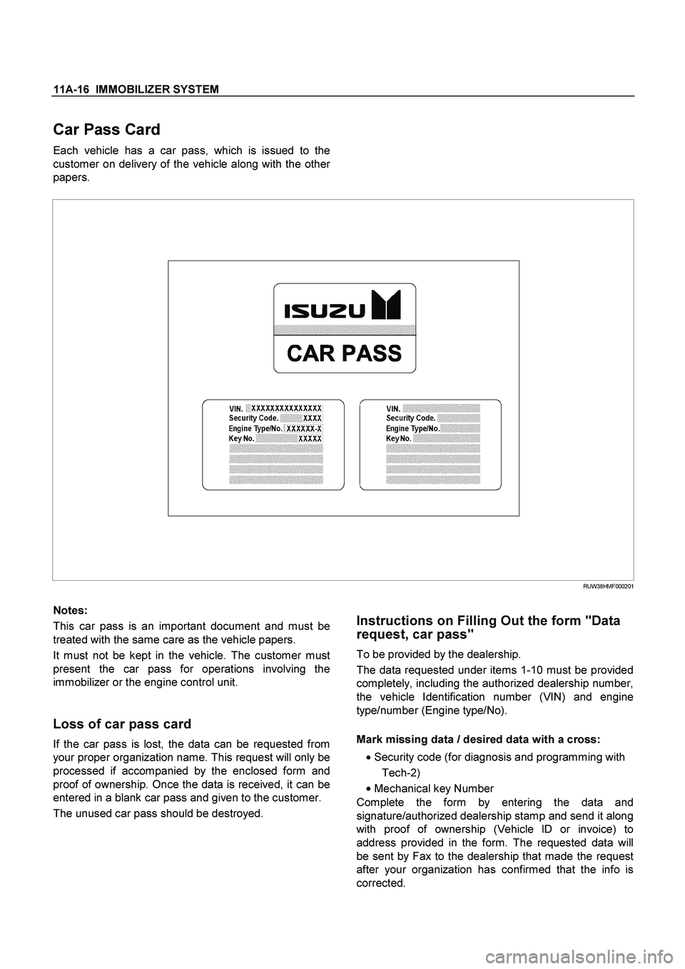
Car Pass Card
Each vehicle has a car pass, which is issued to the
customer on delivery of the vehicle along with the othe
r
papers.
RUW38HMF000201
Notes:
This car pass is an important document and must be
treated with the same care as the vehicle papers.
It must not be kept in the vehicle. The customer must
present the car pass for operations involving the
immobilizer or the engine control unit.
Loss of car pass card
If the car pass is lost, the data can be requested from
your proper organization name. This request will only be
processed if accompanied by the enclosed form and
proof of ownership. Once the data is received, it can be
entered in a blank car pass and given to the customer.
The unused car pass should be destroyed.
Instructions on Filling Out the form "Data
request, car pass"
To be provided by the dealership.
The data requested under items 1-10 must be provided
completely, including the authorized dealership number,
the vehicle Identification number (VIN) and engine
type/number (Engine type/No).
Mark missing data / desired data with a cross:
� Security code (for diagnosis and programming with
Tech-2)
�
Mechanical key Number
Complete the form by entering the data and
signature/authorized dealership stamp and send it along
with proof of ownership (Vehicle lD or invoice) to
address provided in the form. The requested data will
be sent by Fax to the dealership that made the request
after your organization has confirmed that the info is
corrected.