Page 1447 of 4264
 coil, the valve needle opens and the fuel annular
chamber flows through the orifice to")
4JA1/4JH1 ENGINE DRIVEABILITY AND EMISSIONS 6E–75
When control current flows to the timing control valve
(TCV) coil, the valve needle opens and the fuel annular
chamber flows through the orifice to the feed pump inlet.
Consequently, the pressure of the annular chamber
decreases and the hydraulic stopper is moved to the
retard side.
The timing control valve (TCV) acts as a variable
throttle, using the rapid opening and closing (cycling) of
the valve needle in the timing control valve (TCV).
At normal operation, the TCV controls the pressure
acting on the annular chamber so that the hydraulic
stopper cam move to any position, from the retard
position to the advance position. At this time, the duty
ratio is set by the pump control unit (PSG).
Duty ratio is the ratio of the time that the timing control
valve (TCV) is opened to one complete timing control
valve (TCV) operating cycle. A duty ratio change of
100% to 0% is an advance in injection timing. (The
VP44 displays an ON duty ratio.)The engine control module (ECM) contains
characteristic maps of the start of injection,
corresponding to engine operating conditions (engine
load, engine speed and engine coolant temperature).
The pump control unit (PSG) is constantly comparing
the set start of injection timing and the actual start of
injection timing. If there is a difference, the timing
control valve (TCV) is controlled by the duty ratio. (The
actual start of injection timing is determined from the
pump camshaft speed sensor.) (1) Coil
(2) From Annular Chamber
(3) To Feed Pump
(4) Orifice
(5) Valve Needle
Engine Load
Engine Speed
Engine Coolant
TemperatureEngine
Control
Module
(ECM)Pump
Control
Unit
(PSG)
Pump Camshaft
Speed Sensor
Timing
Control
Valve
(TCV)
Page 1589 of 4264
 P0380 (SYMPTOM CODE 4)
(FLASH CODE 66) GLOW RELAY CIRCUIT VOLTAGE LOW
DIAGNOSTIC TROUBLE CODE (DTC) P0380 (SYMPTOM C")
4JA1/4JH1 ENGINE DRIVEABILITY AND EMISSIONS 6E–217
DIAGNOSTIC TROUBLE CODE (DTC) P0380 (SYMPTOM CODE 4)
(FLASH CODE 66) GLOW RELAY CIRCUIT VOLTAGE LOW
DIAGNOSTIC TROUBLE CODE (DTC) P0380 (SYMPTOM CODE 8)
(FLASH CODE 66) GLOW RELAY CIRCUIT VOLTAGE HIGH
Condition for setting the DTC and action taken when the DTC sets
Circuit Description
The voltage on the coil of the relay glow plug is supplied
by the relay engine control module (ECM) main. The
ECM switches glow relay to operate glow plug depends
on the coolant temperature.
In the after glow phase the lamp is not illuminated but
the glow plugs remain active for a certain period
depending on engine coolant temperature.
Diagnostic Aids
An intermittent may be caused by the following:
Poor connections.
Misrouted harness.
Rubbed through wire insulation.
Broken wire inside the insulation.
Check for the following conditions:
Flash
CodeCode Symptom
CodeMIL DTC Name DTC Setting Condition Fail-Safe (Back Up)
66 P0380 4 ON Glo w Re la y Circuit Volta ge
Lo wGlow relay circuit open or
sho rt to ground circuit.No fa il-sa fe fun ctio n.
8 ON Glo w Re la y Circuit Volta ge
HighGlo w re la y circuit short to vo lt-
age circuit.
Page 1829 of 4264
 6A-5
3. Trouble In Fuel System
Symptom Possible Cause Action
Starting motor turns over and spark
occurs but engine does not start. Fuel tank empty Fill
Water in f")
ENGINE MECHANICAL (6VE1 3.5L) 6A-5
3. Trouble In Fuel System
Symptom Possible Cause Action
Starting motor turns over and spark
occurs but engine does not start. Fuel tank empty Fill
Water in fuel system Clean
Fuel filter clogged Replace filter
Fuel pipe clogged Clean or replace
Fuel pump defective Replace
Fuel pump circuit open Correct or replace
Evaporative Emission Control System
circuit clogged Correct or replace
Multiport Fuel Injection System faultyRefer to “Electronic Fuel Injection"
section
4. Engine Lacks Compression
Symptom Possible Cause Action
Engine lacks compression Spark plug loosely fitted Tighten to specified torque
Valve timing incorrect Adjust
Cylinder head gasket defective Replace gasket
Valve incorrectly seated Lap valve
Valve stem seized Replace valve and valve guide
Valve spring weakened or broken Replace
Cylinder or piston rings worn Overhaul engine
Piston ring seized Overhaul engine.
Engine Compression Test Procedure
1. Start and run the engine until the engine reaches
normal operating temperature.
2. Turn the engine off.
3. Remove all the spark plugs.
4. Remove ignition coil fuse (15A) and disable the
ignition system.
5. Remove the fuel pump relay from the relay and
fuse box.
6. Engage the starter and check that the cranking
speed is approximately 300 rpm.
7. Install cylinder compression gauge into spark plug
hole.
8. With the throttle valve opened fully, keep the
starter engaged until the compression gage needle
reaches the maximum level. Note the reading.
9. Repeat the test with each cylinder.
If the compression pressure obtained falls belo
w
the limit, engine overhaul is necessary.
Limit; 1000 kPa (145 psi)
Page 1831 of 4264
ENGINE MECHANICAL (6VE1 3.5L) 6A-7
Rough Engine Running
Symptom Possible Cause Action
Engine misfires periodically Ignition coil layer shorted Replace
Spark plugs fouling Clean or install hotter type plug
Spark plug(s) insulator nose leaking Replace
Fuel injector(s) defective Replace
Engine control module faulty Replace
Engine knocks periodically Spark plugs running too hot Install colder type spark plugs
Engine control module faulty Replace
Engine lacks power Spark plugs fouled Clean
Fuel injectors defective Replace
Mass Airflow Sensor or Intake Airflow
Sensor circuit defective Correct or replace
Engine Coolant Temperature Sensor
or Engine Coolant Temperature
Sensor circuit defective Correct or replace
Engine Control Module faulty Replace
Intake Air Temperature Sensor or
Intake Air Temperature Sensor circuit
defective Correct or replace
Throttle Position Sensor or Throttle
Position Sensor circuit defective Correct or replace
Page 1834 of 4264

Engine Lacks Power
Symptom Possible Cause Action
Trouble in fuel system Fuel Pressure Control Valve not
working normally Replace
Fuel injector clogged Clea")
6A-10 ENGINE MECHANICAL (6VE1 3.5L)
Engine Lacks Power
Symptom Possible Cause Action
Trouble in fuel system Fuel Pressure Control Valve not
working normally Replace
Fuel injector clogged Clean or replace
Fuel pipe clogged Clean
Fuel filter clogged or fouled Replace
Fuel pump drive circuit not working
normally Correct or replace
Fuel tank not sufficiently breathing
due to clogged Evaporative Emission
Control System circuit Clean or replace
Water in fuel system Clean
Inferior quality fuel in fuel system Use fuel of specified octane rating
Engine Control Module supplied poor
voltage Correct circuit
Throttle Position Sensor cable broken
or poor connections Correct or replace
Throttle Position Sensor defective Replace
Mass Airflow Sensor not working
normally Replace
Manifold Absolute Pressure Sensor
not working normally Replace
Intake Air Temperature Sensor not
working normally Replace
Engine Coolant Temperature Sensor
circuit open or shorted Correct or replace
Engine Coolant Temperature Sensor
defective Replace
Engine Control Module defective Replace
Trouble in intake or exhaust system Air Cleaner Filter clogged Replace filter element
Air duct kinked or flattened Correct or replace
Exhaust system clogged Correct or replace
Ignition failure ———— Refer to Hard Start Troubleshooting
Guide
Heat range of spark plug inadequateInstall spark plugs of adequate heat
range
Ignition coil defective Replace
Page 1843 of 4264
ENGINE MECHANICAL (6VE1 3.5L) 6A-19
Engine Oil Pressure Check
1. Check for dirt, Fuel or water in the engine oil.
a. Check the viscosity of the oil.
b. Check the viscosity of the oil.
c. Change the oil if the viscosity is outside the
specified standard.
d. Refer to the “Maintenance and Lubrication"
section of this manual.
2. Check the engine oil level.
The level should fall somewhere between the
“ADD" and the “FULL" marks on the oil level
dipstick.
If the oil level does not reach the “ADD" mark on
the oil level dipstick, engine oil must be added.
3. Remove the oil pressure unit.
4. Install an oil pressure gauge.
5. Start the engine and allow the engine to reach
normal operating temperature (About 80�C).
6. Measure the oil pressure.
Oil pressure should be:
392�
�� �550 kPa (56.9�
�� �80.4 psi) at 3000 rpm.
7. Stop the engine.
8. Remove the oil pressure gauge.
9. Install the oil pressure unit.
10. Start the engine and check for leaks.
Page 1909 of 4264
ENGINE MECHANICAL (6VE1 3.5L) 6A-85
RUW36ASH000501
� With 5�8840�0551�0 Piston pin service set
and a press, press fit the piston pin.
NOTE: Heat the connecting rod small end to a suitable
temperature to ensure smooth installation.
015RX001
Legend
(1) Press Ram
(2) Piston
(3) Connecting Rod
(4) Piston Pin
4. Install piston ring with the piston ring expander.
The No.2 compression ring must be set with the
T2 mark (1) facing up.
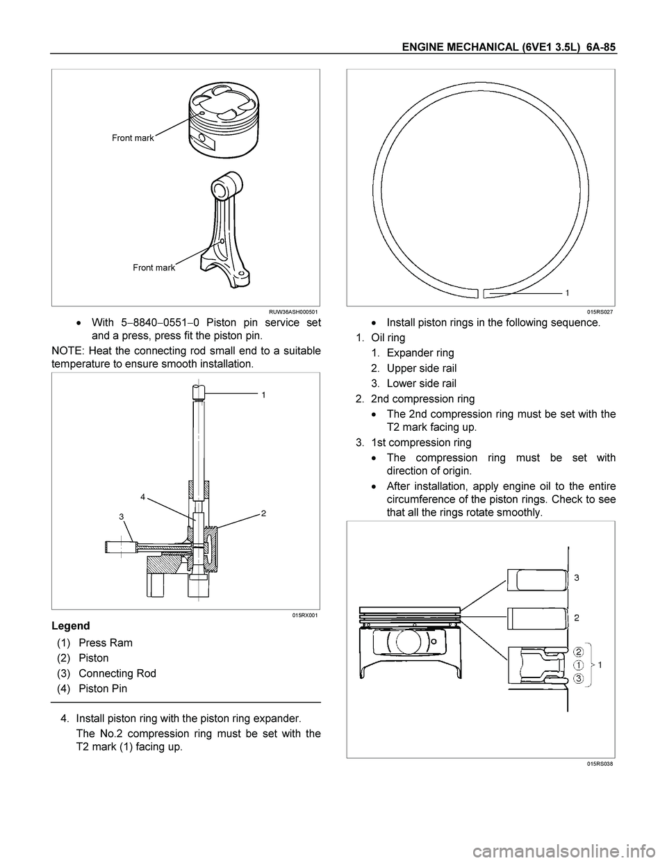
015RS027
� Install piston rings in the following sequence.
1. Oil ring
1. Expander ring
2. Upper side rail
3. Lower side rail
2. 2nd compression ring
� The 2nd compression ring must be set with the
T2 mark facing up.
3. 1st compression ring
� The compression ring must be set with
direction of origin.
� After installation, apply engine oil to the entire
circumference of the piston rings. Check to see
that all the rings rotate smoothly.
015RS038
Page 1929 of 4264
ENGINE COOLING (6VE1 3.5L) 6B-5
Diagnosis
Engine Cooling Trouble
Symptom Possible Cause Action
Engine overheating Low Engine Coolant level Replenish
Thermo meter unit faulty Replace
Faulty thermostat Replace
Faulty Engine Coolant temperature
sensor Repair or replace
Clogged radiator Clean or replace
Faulty radiator cap Replace
Low engine oil level or use of
improper engine oil Replenish or change oil
Clogged exhaust system Clean exhaust system or replace
faulty parts
Faulty Throttle Position sensor Replace throttle valve assembly
Open or shorted Throttle Position
sensor circuit Repair or replace
Damaged cylinder head gasket Replace
Engine overcooling Faulty thermostat Replace
Engine slow to warm–up Faulty thermostat Replace
Thermo unit faulty Replace
 6A-7
Rough Engine Running
Symptom Possible Cause Action
Engine misfires periodically Ignition coil layer shorted Replace
Spark plugs fouling Clean or install hott")
 6A-19
Engine Oil Pressure Check
1. Check for dirt, Fuel or water in the engine oil.
a. Check the viscosity of the oil.
b. Check the viscosity of the oil.
c. Change")
 6B-5
Diagnosis
Engine Cooling Trouble
Symptom Possible Cause Action
Engine overheating Low Engine Coolant level Replenish
Thermo meter unit faulty Replace
Faulty")