Page 3439 of 4264

POWER-ASSISTED STEERING SYSTEM 3B-9
4. Install all the lines and hoses. Fill the system with
new power steering fluid and bleed the system as
described in Bleeding The Power Steering System.
Operate the engine for about 15 minutes.
Remove the pump return line at the pump inlet and
plug the connection on the pump. While refilling the
reservoir, check the draining fluid for contamination.
If foreign material is still evident, replace all lines,
disassemble and clean or replace the powe
r
steering system components. Do not re-use any
drained power steering fluid.
Steering Wheel Free Play Inspection
060R300016
1. With the tires in the straight-ahead position, check
the amount of steering wheel play by turning the
wheel in both directions until the tires begin to move.
NOTE: The wheel free play should be checked with the
engine running.
Free play: 0 - 30 mm (0 - 1.18 in)
2.
Also check the steering wheel for play and
looseness in the mount by moving it back and forth
and sideways. When test driving, check for hard
steering, steering shimmy and tendency to pull to
one side.
Front End Alignment Inspection and
Adjustment
Toe-in Adjustment
Toe-in: Refer to Section 3A FRONT ALIGNMENT
1. To adjust the toe-in angle, loosen the lock nuts (2)
on the tie rod (1) and turn the tie rod. Turn both rods
the same amount, to keep the steering wheel
centered .
This illustration is based on the RHD model.
431R30006
2. Tighten the lock nut to the specified torque.
Torque:
92 - 104 N�
�� �m (9.4 - 10.6 kg�
�� �m/68 - 77 lb ft)
Page 3440 of 4264
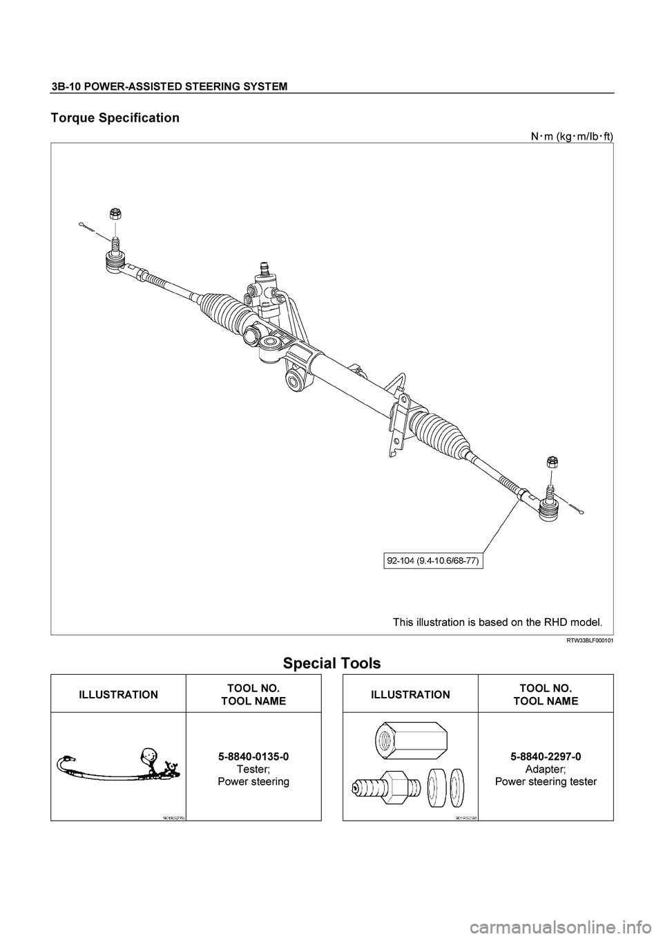
3B-10 POWER-ASSISTED STEERING SYSTEM
Torque Specification
N�
m (kg�
m/Ib�
ft)
This illustration is based on the RHD model. RTW33BLF000101
Special Tools
ILLUSTRATION
TOOL NO.
TOOL NAME
ILLUSTRATION
TOOL NO.
TOOL NAME
5-8840-0135-0
Tester;
Power steering
5-8840-2297-0
Adapter;
Power steering tester
Page 3441 of 4264
POWER-ASSISTED STEERING SYSTEM 3B-11
Power Steering Unit
Power Steering Unit and Associated Parts
This illustration is based on the RHD model. 431R300016
Legend
(1) Crossmember
(2) Power Steering Unit Assembly
(3) Bracket
(4) Universal joint (Steering shaft)
Removal
1. Remove the universal joint assembly.
Make a setting mark across the coupling flange and
steering unit to ensure reassembly of the parts in
the original position.
2. Drain power steering fluid.
3. Remove the tie rod end assembly from knuckle.
Use tie rod end remover 5-8840-2005-0.
Page 3442 of 4264

3B-12 POWER-ASSISTED STEERING SYSTEM
901RW270
4. Disconnect the feed line and return line from
steering unit.
Remove the clips on the crossmember and frame.
Wire the power steering line to frame.
NOTE: Take care to prevent foreign matter from entr
y
when disconnect the power steering line.
5. Remove the power steering unit from the
crossmember.
Installation
1. Install power steering unit to crossmember.
Tighten fixing bolt and nut to specified torque.
Torque:
106 – 126 N�
�� �m (10.8 – 12.8 kg�
�� �m/78 - 93 lb ft)
Torque:
198 - 242 N�
�� �m (20.2 – 24.7 kg�
�� �m/146 - 178 lb ft)
2. Connect the feed line and return line.
Torque:
20 - 29 N�
�� �
m (2.0 – 3.0 kg�
�� �
m/14 - 22 lb ft)
3. Install tie-rod end assembly to knuckle.
Torque:
88 – 127 N�
�� �m (9.0 – 13.0 kg�
�� �m/65 - 94 lb ft)
4.
Align the setting marks on the universal joint
(applied at disassembly) with the setting marks on
the power steering unit. Connect the universal joint
assembly to the power steering unit. Temporaril
y
tighten the universal joint bolts on the universal joint
assembly side.
5. Tighten the universal joint bolts (bolts at either end
of the joint temporarily tightened in Step 1 and 2) to
the specified torque.
6. Install the stone guard.
7. Bleed the system.
Refer to Bleeding the Power Steering System in this
section.
Page 3443 of 4264
POWER-ASSISTED STEERING SYSTEM 3B-13
Power Steering Unit Disassembled View
This illustration is based on the RHD model. 440R300003
Legend
(1) Tie-rod End
(2) Lock Nut
(3) Clip
(4) Bellows
(5) Band
(6) Tie-rod Assembly
(7) Oil Line
(8) Inner Ball Joint Assembly
(9) Tab Washer
(10) Mounting Rubber
(11) Housing Assembly
Disassembly
NOTE: The valve housing is made of aluminum and
care should be exercised when clamping in a vise, etc.
to prevent distortion or damage.
1. Loosen lock nut and remove tie-rod end.
2. Remove clip and band, then remove bellows.
3. Remove tie-rod assembly.
To remove, move the boot toward the tie-rod end,
then remove tab washer.
4. Remove oil line, mounting rubber and dust cover.
Inspection and Repair
Inspect the following parts for wear, damage or any
abnormal conditions.
Page 3444 of 4264

3B-14 POWER-ASSISTED STEERING SYSTEM
Tie-rod End
If looseness or play is found when checked by moving
the end of ball joint at tie-rod end, replace tie-rod end.
Tie-rod Assembly
If the resistance is insufficient or play is felt when
checked by moving the ball on the tie-rod, replace the
tie-rod assembly.
Rubber Parts
If wear or damage is found through inspection, replace
with new ones.
Reassembly
1. Install mounting rubber and dust cover (If removed).
2. Install oil line.
Torque: 10 - 15 N�
�� �m (1.0 – 1.5 kg�
�� �m/87 - 130 lb in)
3. Install tie-rod assembly with tab washer.
Apply grease to ball joint, install tie-rod and tab
washer, then tighten to specified torque.
Torque: 69 - 98 N�
�� �m (7.0 – 10.0 kg�
�� �m/51 - 72 lb ft)
After tightening, bend tab washer against width
across flat of inner ball joint.
4.
Apply a thin coat of grease to the shaft for smooth
installation. Then install bellows.
5. Install band and clip.
6. Install tie-rod end and tighten lock nut.
Torque:
92 - 104 N�
�� �m (9.4 – 10.6 kg�
�� �m/68 - 77 lb ft)
Main Data and Specifications
General Specifications
2WD 4WD
Power steering Without With
Type Rack and pinion
Rack stroke mm (in) 138 (5.43) 138 (5.43) 152 (5.98)
Steering unit
Lock to lock 4.84 3.38 3.26
Page 3445 of 4264
POWER-ASSISTED STEERING SYSTEM 3B-15
Torque Specifications
N�
m (kg�
m/Ib�
ft)
This illustration is based on the RHD model. RTW33LF000201
Special Tools
ILLUSTRATION
TOOL NO.
TOOL NAME
5-8840-2005-0
(J-29107)
Tie rod end remover
Page 3446 of 4264
3B-16 POWER-ASSISTED STEERING SYSTEM
Power Steering Pump
Power Steering Pump and Associated Parts (4JH1-TC, 4JA1-TC, 4JA1-L)
442R300002
Legend
(1) Pump Assembly
(2) Hose, Suction
(3) Hose, Flexible
(4) Bolt
Removal
1. Remove the drive belt.
2. Remove the pulley
3. Place a drain pan below the pump.
4. Disconnect the suction hose.
5. Disconnect the flexible hose.
6. Remove the power steering fixing bolt and remove
the pump assembly.
Installation
1. Install the pump assembly to the pump braket,
tighten the fixing bolt to the specified torque.
Torque: 34 - 46 N·m (3.5 – 4.7 kg·m/25 - 34 lb ft)
2. Install the flexible hose.
Tighten the eye bolt to specified torque.
Torque: 49 - 59 N·m (5.0 – 6.0 kg·m/36 - 43 lb ft)
3. Install the pulley and tighten the bolt to the specified
torque.
Torque: 26 - 30 N·m (2.7 –3.1 kg·m/20 - 22 lb ft)
4. Install the drive belt.
5. Connect the suction hose, then fill and bleed system.
Refer to Bleeding the Power Steering System in this
section.
 Crossmember
(2) Power Ste")
 Tie-rod End
(2) Lock Nut
(3) Clip
(4) Bellows
(")

442R300002
Legend
(1) Pump Assembly
(2) Hose, Suction
(3) Hose,")