Page 3003 of 4264

�
�� �
In order to obtain maximum performance and longest service life from your ISUZU vehicles, it is very important")
MAINTENANCE AND LUBRICATION 0B-15
RECOMMENDED FLUIDS AND LUBRICANTS (For EUROPE)
�
�� �
In order to obtain maximum performance and longest service life from your ISUZU vehicles, it is very important to
select and use correctly best lubricants and diesel fuels.
When lubricating, be sure to use ISUZU genuine lubricants or recommended lubricants listed below, according to
the maintenance schedule for each vehicle model.
LUBRICATION/FLUID GRADE
API ACEA OTHER
Diesel engine crankcase B2/B3
E2/E3
Manual transmission
Transfer case B2/B3
E2/E3
Differential
Shift on the fly system
(GL-5 only)
GL-5 BESCO GEAR OIL SH (80W-90, 90, 140) (ISUZU GENUINE)
BESCO SHIFT ON THE FLY (75W-90) (ISUZU GENUINE)
GEAR OIL GX (85W-90) (EXXON / ESSO)
MOBILUBE HD (80W-90, 85W-140) (MOBIL)
THURBAN GL-5 EP (80W-90, 85W-140) (CALTEX)
SPIRAX HD (90, 140) (SHELL)
TRANSELF TYPE B (80W-90, 85W-140) (ELF)
TRANSMISSION TM (80W-90, 85W-140) (TOTAL)
Differential
(Limited Slip Differential)
GL-5 * Limited
Slip
Differential
Gear
Lubricant
BESCO GEAR OIL LSD (140) (ISUZU GENUINE)
GEAR OIL LSA (90) (EXXON/ESSO)
MOBILUBE HD LS (80W-90) (MOBIL)
GEAR OIL LSD (90) (CALTEX)
TRANSELF TYPE BLS (90) (SHELL)
TRANSMISSION DA (85W-90) (ELF)
HYPOY LS (90) (TOTAL)
Automatic transmission
Power steering
DEXRON II, III
Propeller shaft sliding yoke
Universal joint
(General purpose grease in
Molybdenum) NLGI #2 or #3
multi purpose type grease
containing molybdenum disulfide
Engine cooling system Good quality ethylene glycol antifreeze or GM spec.
6033-M or equivalent
* If GL-5 Limited Slip Differential Lubricant is not available, use GL-5 Lubricant together with Limited Slip Differential Lubricant additive (Parts No. 8-01052-358-0) or
equivalent.
FLUID TYPE
Clutch and brake fluid reservoir Besco brake fluid (For light duty)
Hydraulic brake fluid SAE J1703
FMVSS 116 DOT.3 grade
DIESEL FUEL/APPLICABLE STANDARD
JIS (JAPANESE INDUSTRIAL STANDARD)
DIN (DEUTSCHE INDUSTRIE NORMEN)
SAE (SOCIETY OF AUTOMOTIVE ENGINEERS)
BS (BRITISH STANDARD) Based on K2204 GAS OIL
Based on EN590: 1997L
Based on SAE J-313C
Based on BS EN590: 1997
NOTE:
Use the applicable standard or equivalent for diesel fuels.
�
�
�
Page 3296 of 4264
11A-10 IMMOBILIZER SYSTEM
Parts Location
LTW3BAMF000101
Legend
(1)
Immobilizer Control Unit (ICU)
(2)
Immobilizer Coil
(3)
Cross Beam
(4)
Steering Shaft
Page 3415 of 4264
WORKSHOP MANUAL
TF SERIES
STEERING SUSPENSION,
WHELLS AND TIRES
SECTION 3
Page 3418 of 4264

3A-2 FRONT ALIGNMENT
Front End Alignment Inspection and
Adjustment
General Description
“Front End Alignment” refers to the angular
relationshipbetween the front wheels, the front suspension
attachingparts and the ground.
Proper front end alignment must be maintained in order
toinsure efficient steering, good directional stability and
toprevent abnormal tire wear.
The most important factors of front end alignment arewheel
toe-in, wheel camber and axle caster.
Camber:
This illustration shows view from the front of the vehicle.
Camber is the vertical tilting inward or outward of the front
wheels. When the wheels tilt outward at the top, the camber is
positive (+). When the wheels tilt inward at the top, the camber
is negative (-). The amount of tilt measured in degrees from
the vertical is called the camber angle (1). If camber is extreme
or unequal between the wheels, improper steering and
excessive tire wear will result. Negative camber causes wear
on the inside of the tire, while positive camber causes wear to
the outside.
Caster:
This illustration shows view from the side of the vehicle.
Caster (1) is the vertical tilting of the wheel axis either
forward or backward (when viewed from the side of the
vehicle). A backward tilt is positive (+) and a forward tilt is
negative (-). On the short and long arm type suspension
you cannot see a caster angle without a special instrument, but
if you look straight down from the top of the upper control arm
to the ground, the ball joints do not line up (fore and aft) when
a caster angle other than 0 degree is present. With a positive
angle, the lower ball joint would be slightly ahead (toward the
front of the vehicle) of the upper ball joint center line.
Toe-in:
This illustration shows view from the top of the vehicle.
Toe-in is the measured amount the front wheels are turned in.
The actual amount of toe-in is normally a fraction of a degree.
Toe-in is measured from the center of the tire treads or from
the inside of the tires. The purpose of toe-in is to insure parallel
rolling of the front wheels and to offset any small deflections of
the wheel support system which occurs when the vehicle is
rolling forward. Incorrect toe-in results in excessive toe-in and
unstable steering. Toe-in is the last alignment to be set in
the front end alignment procedure.
Page 3419 of 4264

FRONT ALIGNMENT 3A-3
Inspection
Before making any adjustments affecting caster, camber or
toe-in, the following front end inspection should be made.
1. Inspect the tires for proper inflation pressure. Refer to
Main Data and Specifications in Wheel and Tire System
section.
2. Make sure that the vehicle is unlade condition (Withno
passenger or loading).
3. Make sure that the spare tire is installed at the normal
position.
4. Inspect the front wheel bearings for proper adjustment.
Refer to Front Hub and Disc Overhaul in Suspension
section.
5. Inspect the ball joints and tie rod ends. If excessive
looseness is noted, correct before adjusting. Refer to
Steering Linkage in this section.
6. Inspect the wheel and tires for run-out. Refer to Wheel
Replacement in Wheel and Tire System section.
7. Inspect the trim height. If not within specifications, the
correction must be made before adjusting caster.
8. Inspect the steering unit for looseness at the frame.
9. Inspect shock absorbers for leaks or any noticeable noise.
Refer to Shock Absorber in Suspension section.
10. Inspect the control arms or stabilizer bar attachment fo
r
looseness. Refer to Suspension section.
11. Inspect the front end alignment using alignment equipment.
Follow the manufacturer’s instructions.
12. Park the vehicle on a level surface.
Page 3424 of 4264

3A-8 FRONT ALIGNMENT
Toe-in Adjustment
Measurement should be taken with the vehicle on a surface
plate.
If a surface plate is not available, toe-in should be checked
with the vehicle parked on a level floor.
1. Set front wheels to straight ahead position.
2. Align the toe-in gauge with center height of each wheel a
t
front end.
3.
Apply center marks to each wheel, then take measurement
of distance A between the center marks on each wheel.
4. Slowly move the vehicle rearward until the center marks
reach the rear end position.
5. Take measurement of distance B between the cente
r
marks at rear end.
The toe-in can be calculated with next formula.
Toe-in = B - A
Toe-in mm (in)
4�
2
(Except high ride suspension) 0�
2 (0�
0.08)
To adjust the toe-in angle, loosen the lock nuts (2) on the tie
rod (1) and turn the tie rod. Turn both rods the same amount,
to keep the steering wheel centered.
Lock Nut Torque N�
m (kgf�
m/lb�
ft)
98�6.0 (10.0�0.6 / 72.3�4.3)
RTW330SH000101
Trim Height
Trim Height : at Curb Weight (Reference Data)
Trim height (Z) = A - B
Front mm (in)
Z
105(4.13)
Page 3425 of 4264
FRONT ALIGNMENT 3A-9
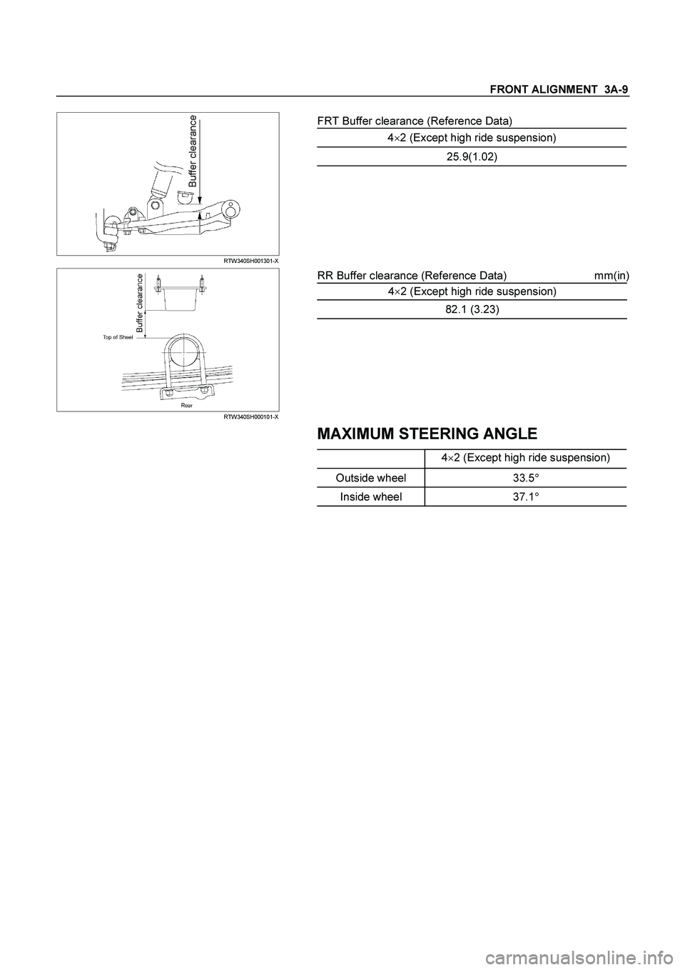
RTW340SH001301-X
FRT Buffer clearance (Reference Data)
4�2 (Except high ride suspension)
25.9(1.02)
RTW340SH000101-X
RR Buffer clearance (Reference Data) mm(in)
4�
2 (Except high ride suspension)
82.1 (3.23)
MAXIMUM STEERING ANGLE
4�
2 (Except high ride suspension)
Outside wheel 33.5�
Inside wheel 37.1�
Page 3428 of 4264

3A-12 FRONT ALIGNMENT
Toe-in Adjustment
Measurement should be taken with the vehicle on a surface
plate.
If a surface plate is not available, toe-in should be checked
with the vehicle parked on a level floor.
1. Set front wheels to straight ahead position.
2. Align the toe-in gauge with center height of each wheel a
t
front end.
3.
Apply center marks to each wheel, then take measurement
of distance A between the center marks on each wheel.
4. Slowly move the vehicle rearward until the center marks
reach the rear end position.
5. Take measurement of distance B between the cente
r
marks at rear end.
The toe-in can be calculated with next formula.
Toe-in = B - A
Toe-in mm (in)
4�2 (High ride suspension)
4�4 0�2 (0�0.08)
To adjust the toe-in angle, loosen the lock nuts (2) on the tie
rod (1) and turn the tie rod. Turn both rods the same amount,
to keep the steering wheel centered.
Lock Nut Torque N�
m (kgf�
m/lb�
ft)
98�6.0 (10.0�0.6 / 72.3�4.3)
RTW330SH000201
Trim Height
Trim Height : at Curb Weight
Trim height (Z) = A - B
mm (in)
Z
140�
5 (5.51)

Immobilizer Control Unit (ICU)
(2)
Immobilizer Coil
(3)
Cross Beam
(4)
Steering Shaft")